
Latch device with variable latching resistance and method

a latching resistance and variable technology, applied in the field of cargo container securement devices, can solve the problem of high impact force for all

Inactive Publication Date: 2010-12-02
HOLLAND CO
View PDF20 Cites 21 Cited by
  • Summary
  • Abstract
  • Description
  • Claims
  • Application Information

AI Technical Summary

Benefits of technology

[0020]In applications where typical ISO type containers are used and are desired to be secured to railcars with relatively light weight decks, a device with one resilient spring element is expected to be sufficient to perform as desired. A low cost, constant diameter spring with a linear stiffness rate may be selected to provide the desired securement forces.
[0021]The geometry and weight of typical ISO type containers along with typical railcar operational speeds and conditions are some of the factors that are used in the design of a railcar and its deck. Light weight decks are desirable due to their inherent reduced costs of manufacture. Therefore, the device is allowed to be tailored with a low cost, constant diameter spring with an inherent linear stiffness rate so as to provide the desired hold down forces.
[0024]The present invention provides an easy solution to this noted problem by allowing one to selectively and telescopically install one or more compression coils into the latch device depending on the application thereby simultaneously maximizing effective use of space defined by the coil structures; and tailoring the force characteristics for a given securement application.
[0025]The device according to the present invention provides one or more coils to selectively provide a linear resistance or a variable resistance. The variable resistance would be selected to provide relatively low startup actuation force to prevent stiction and as the latch retracts slightly after initial movement, the latch would retract and come into contact with the second resilient spring element providing additional stiffness resulting in a higher total securement force than would be possible with only one resilient spring element.
[0028]The latch retracts into the latch-receiving top portion of the housing as the container translates toward the vehicle deck or similar support surface. As the latch retracts, it may selectively contact additional coils telescopically received by the first compression coil and successively shorter in length than the first compression coil. Additional coil displacements are effected by latch retraction and additional resistance to displacement ratios are thereby achieved. Once the latch-actuating opening of the corner casting translates past the tip of the latch at a maximized resistance to displacement ratio or slope, the latch secures the corner casting as the compressive spring element(s) are restored to a relaxed position and the first compression coil is restored to its biased starting position.
[0030]The latch device according to the present invention thus functions to secure cargo containers to a vehicle deck or similar surface and essentially comprises a housing having a container penetrating upper portion that contains or receives a latch mechanism that extends outwardly and laterally from the upper portion of the housing to engage a cargo container corner casting. The lower portion of the housing comprises a typically flat base that is tailored to interface with a vehicle deck or similar surface. One or more resilient compression coils extend between the latch mechanism and the housing to provide the linear or variable resistance required by the application.

Problems solved by technology

Startup stiction in a latch device creates rough startup operation which results in higher than necessary impact forces to all of the items involved and is thus not desired.

Method used


Image

  • Latch device with variable latching resistance and method
  • Latch device with variable latching resistance and method
  • Latch device with variable latching resistance and method

Examples


Embodiment Construction

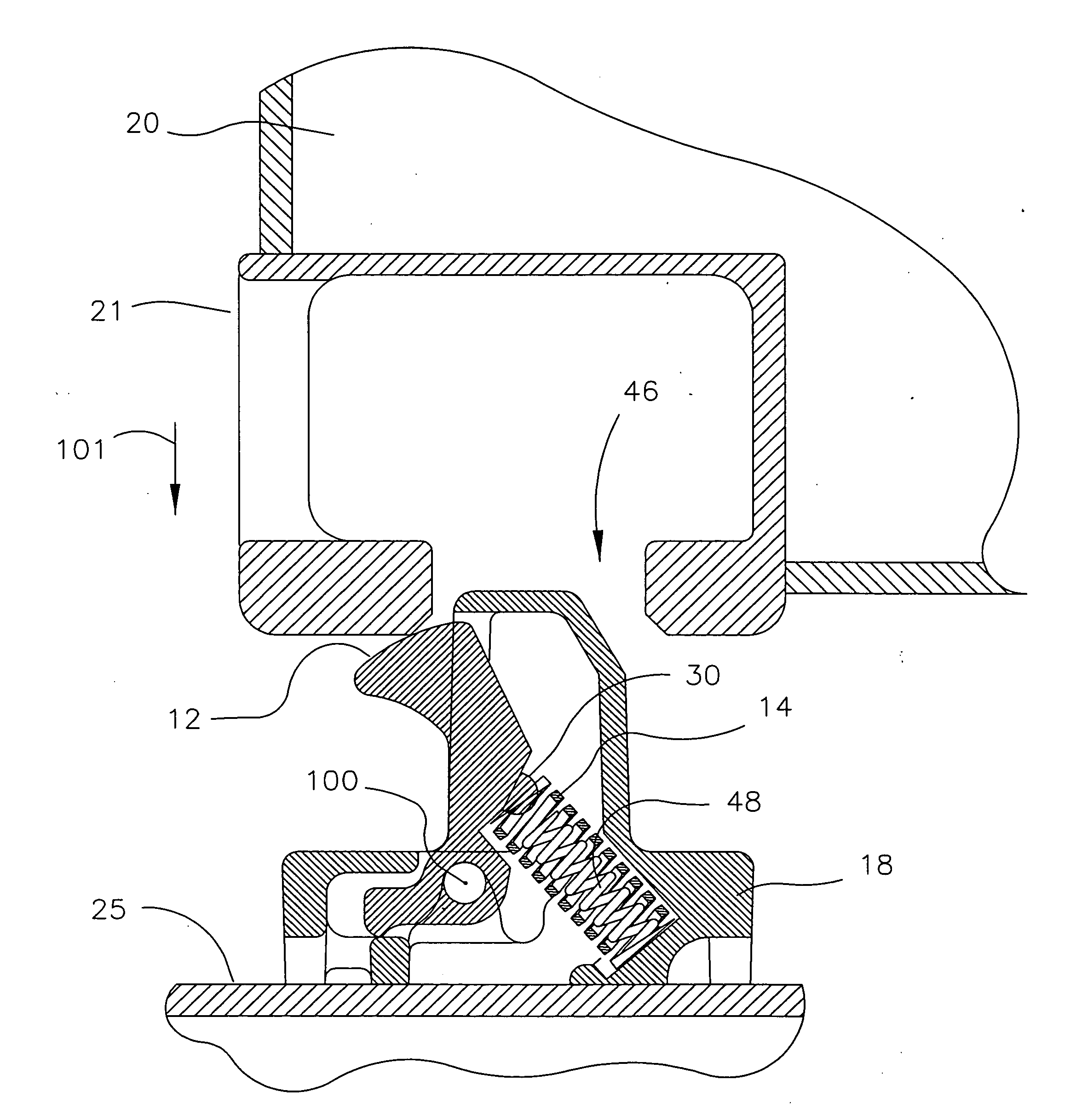
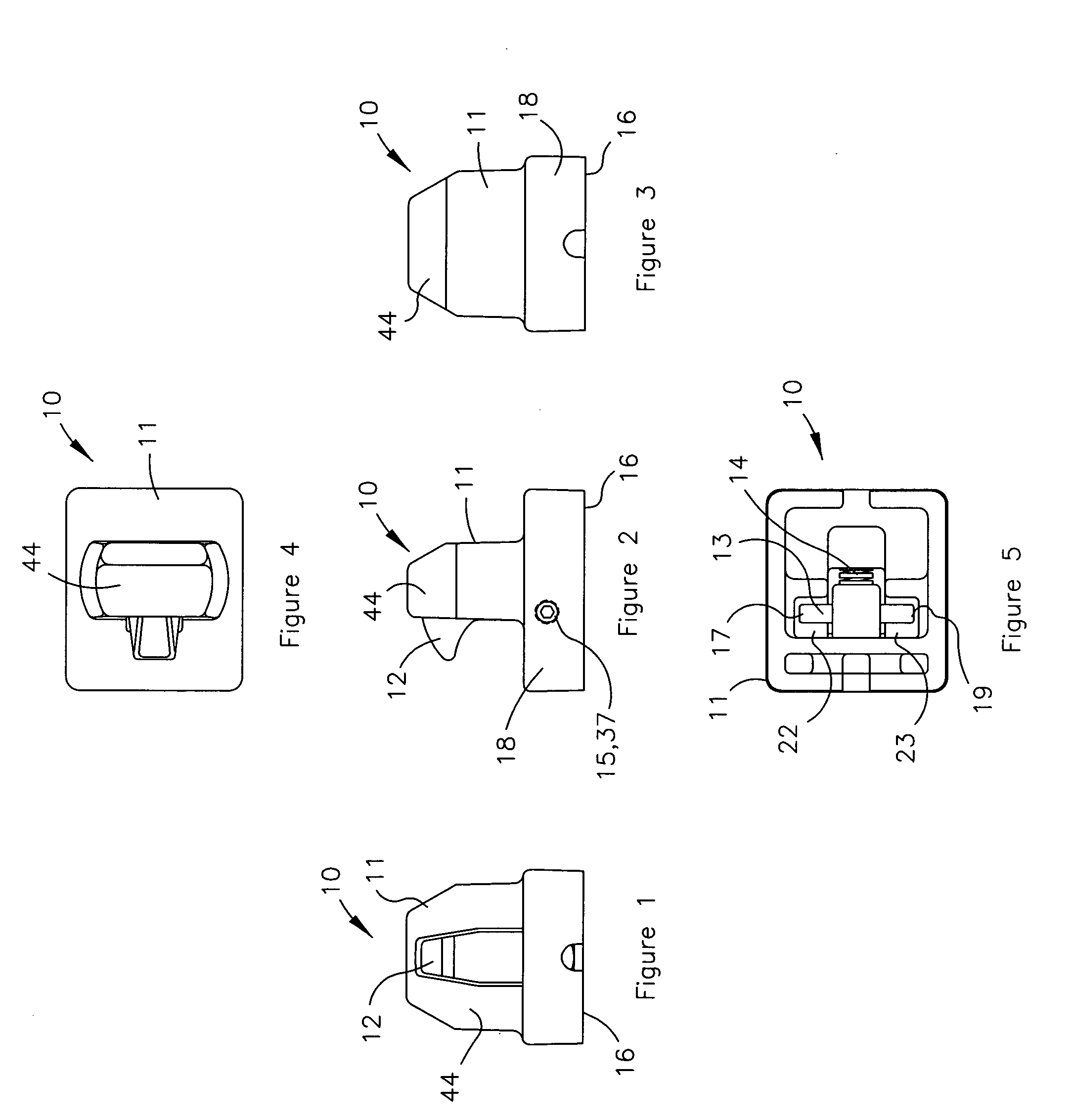
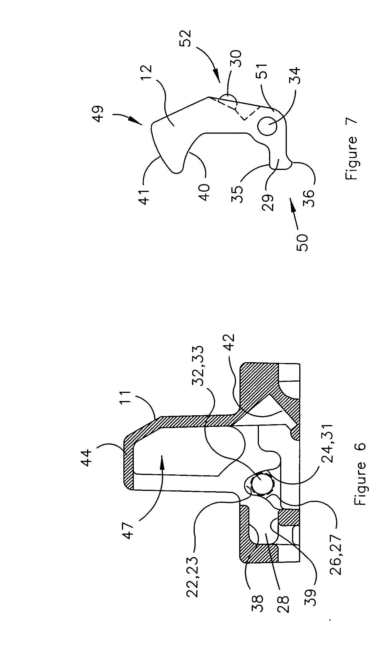
[0071]Referring now with more specificity to the drawings, the present invention provides a latch device or assembly 10 for releasably securing a cargo container (not specifically illustrated) to a support surface (as at 25). The latch device includes or comprises a housing 11, a latch member 12, a pin 13, a first compression spring 14, and two side screws as at 15 and 37. One side screw 15 or 37 is on each side of housing 11. The housing 11 comprises an upper, container-penetrating shell as at 44 and an inner, coil-receiving cavity as at 42. The shell 44 is receivable by a latch-actuating opening 46 and defines an open-face, latch-receiving cavity as at 47.

[0072]An assembled frontal view of the latch device 10 is shown in FIG. 1, and an assembled side lateral view of the latch device 10 is shown in FIG. 2. The housing 11 further comprises a base bottom 16 that interfaces with the deck or vehicle or similar planar surface as at surface 25, and a base 18 which is typically spaced bet...


PUM


Abstract

A latch device releasably secures a container to a support surface. The device comprises a housing, a latch, interchangeable spring sets, and a pin. The housing comprises an upper shell and an inner coil-receiving cavity. The shell defines a latch-receiving cavity. The latch comprises an upper latch end and a coil-engaging portion. The coil-engaging portion comprises coil-aligning structure. At least one compression coil is received within the coil-receiving cavity and placed into engagement with the coil-engaging portion so as to bias the upper latch end exterior to shell via the latch-receiving cavity. The coil-aligning structure enhances axial alignment of each coil during coil compression. The pin pivotally connects the latch to the housing for enabling pivotal movement of the latch under selectively varied spring resistance for targeted applications. The coil(s) thus enable the user to vary latching forces during latching securement and release depending to the targeted loads and conditions.

Description

BACKGROUND OF THE INVENTION[0001]1. Field of the Invention[0002]The present invention relates to container securement devices and more particularly to improvements in cargo container securement devices providing automatic securement and release of a cargo container.[0003]2. Discussion of Prior Art[0004]Containerized lading has become immensely popular due to advantages such as labor savings resulting from decreased cargo handling. Modular or standardized containers may be shipped from point to point using a variety of different carriers including rail cars, trucks and ships. Such cargo containers are conventionally provided with corner castings including locking openings used in securing the containers to the various types of vehicles upon which they are loaded.[0005]One type of container securement device used in the past is a container pedestal including a base portion upon which a corner of the container rests, as well as vertically extending walls within which a corner of the co...

Claims


Application Information

Patent Timeline
IPC IPC(8): B60P1/64
CPCB60P7/132B61D45/007
Inventor BREWSTER, JOHN B.
Owner HOLLAND CO
Learn More