
Network relay apparatus and inter-network relay method

Active Publication Date: 2010-12-02
ALAXALA NETWORKS
View PDF6 Cites 22 Cited by
  • Summary
  • Abstract
  • Description
  • Claims
  • Application Information

AI Technical Summary

Benefits of technology

[0008]In order to solve at least part of the problems described above, it is required to provide simple and easy multicast communication between multiple different networks using an unspecified number of transmission devices.

Problems solved by technology

This leads to the cost increase and the rather complicated network management.
The PIM-SSM protocol technique requires previous specification of a transmission device of multicast data and is not capable of receiving multicast packets from an unspecified number of transmission devices.
There is difficulty in such settings especially when multiple different networks are managed by different network administrators.
This may represent a breach of security in each VPN.
The combined use of MSDP with PIM-SM increases the number of protocols to be managed and thereby undesirably complicates the network management.

Method used


Image

  • Network relay apparatus and inter-network relay method
  • Network relay apparatus and inter-network relay method
  • Network relay apparatus and inter-network relay method

Examples


first embodiment

Configuration of Multicast Network

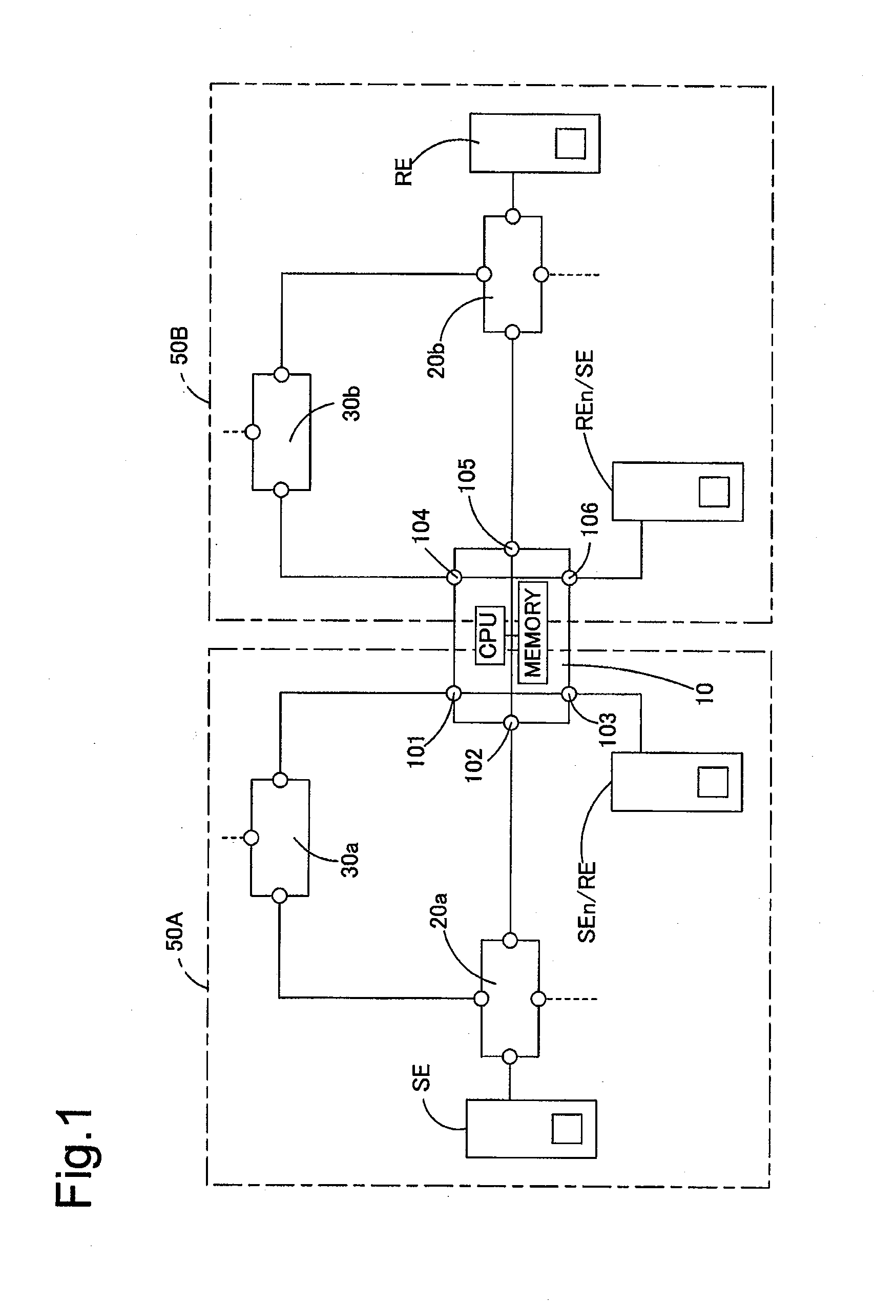
[0054]FIG. 1 is an explanatory diagrammatic representation of a multicast network configuration according to a first embodiment of the invention. A network relay router 10 as one embodiment of the network relay apparatus according to the invention establishes and has a first VPN (virtual private network) 50A and a second VPN 50B. Each of the first and the second VPNs 50A and 50B forms a PIM-SM multicast network. The first VPN 50A is constructed by routers 20a and 30a and the network relay router 10, wherein the router 30a functions as a rendezvous point. The second VPN 50B is constructed by routers 20b and 30b and the network relay router 10, wherein the router 30b functions as a rendezvous point. The first VPN 50A and the second VPN 50B respectively correspond to the first network and the second network in the claims of the invention.

[0055]In the first VPN 50A, the router 30a functioning as the rendezvous point is connected with the router 20a and ...

second embodiment

[0108]Inter-VRF multicast relay in a network configuration where a transmission device SE and a receiving device RE of multicast packets are directly connected to a network relay router 10 establishing multiple VPNs is described as a second embodiment according to the invention. The network relay router 10 of the second embodiment has the same internal structure as that of the network relay router 10 of the first embodiment. The like components are expressed by the like numerals and symbols and are not specifically described here.

[0109]FIG. 20 is an explanatory diagrammatic representation of the network configuration where the transmission device SE and the receiving device RE of multicast packets are directly connected to the network relay router 10 establishing the multiple VPNs (virtual private networks). The transmission device SE in a first VPN 50A as a first network and the receiving device RE in a second VPN 50B as a second network are connected respectively to an input / outpu...

third embodiment

[0120]As in the network configuration of the first embodiment, in a network configuration of a third embodiment according to the invention, a multicast group address as an inter-VRF relay subject, a sender VRF name, and a receiver VRF name are registered in a network relay router 10 establishing or building multiple VPNs. The network relay router 10 of the third embodiment sends a PIM(*,G)join message to a rendezvous point in a sender VPN, in response to reception of a PIM(*,G)join message from a router 20b. Namely the setting of route information in the network relay router 10 alone does not trigger transmission of the PIM(*,G)join message to the rendezvous point in the sender VPN. Namely a multicast packet sent from a transmission device SE is not relayed to the network relay router 10 immediately after completion of the setting. Inter-VRF multicast relay starts after reception of a join request message from a receiving device RE. This arrangement desirably restricts or prevents u...


PUM


Abstract

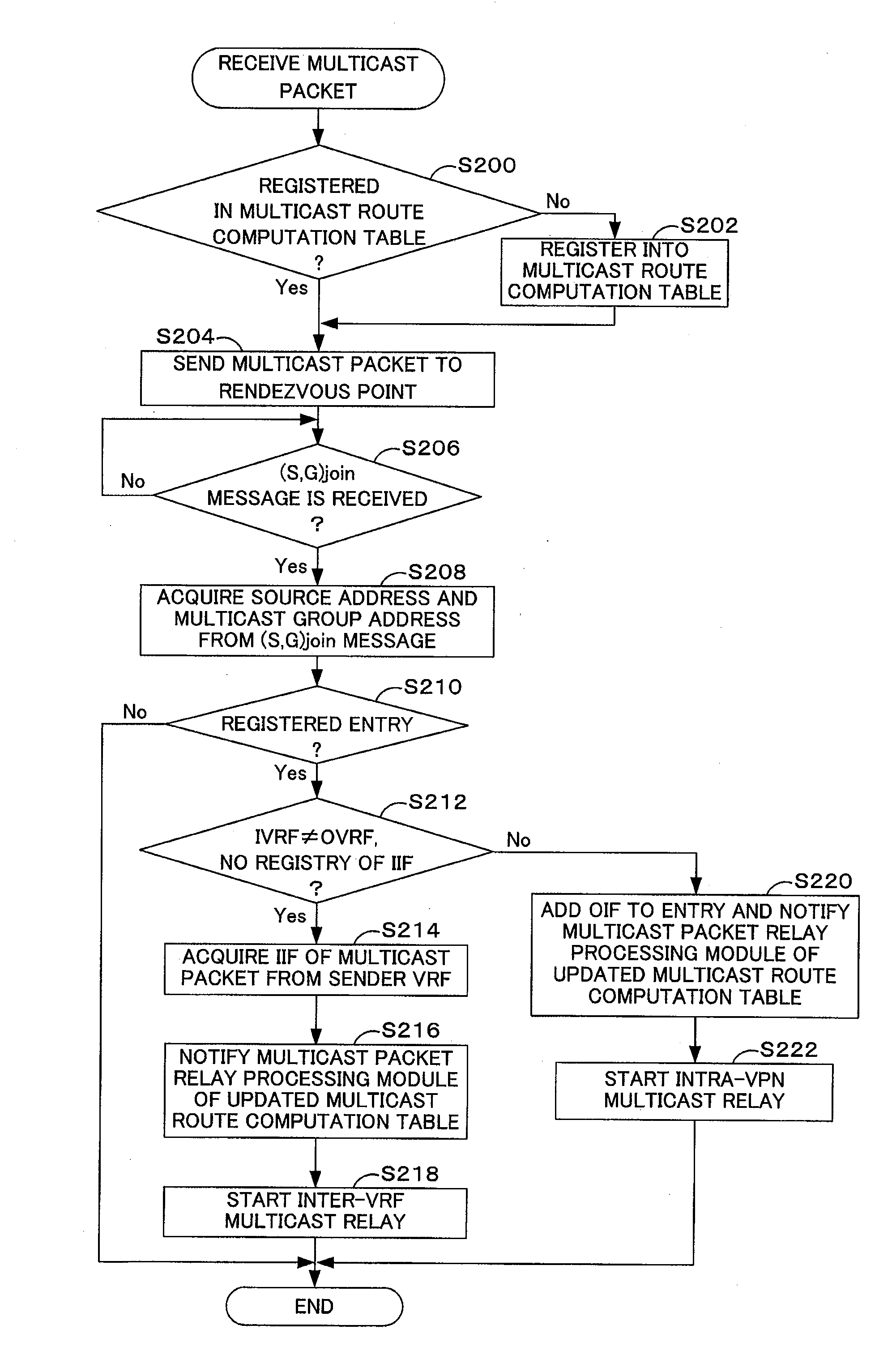
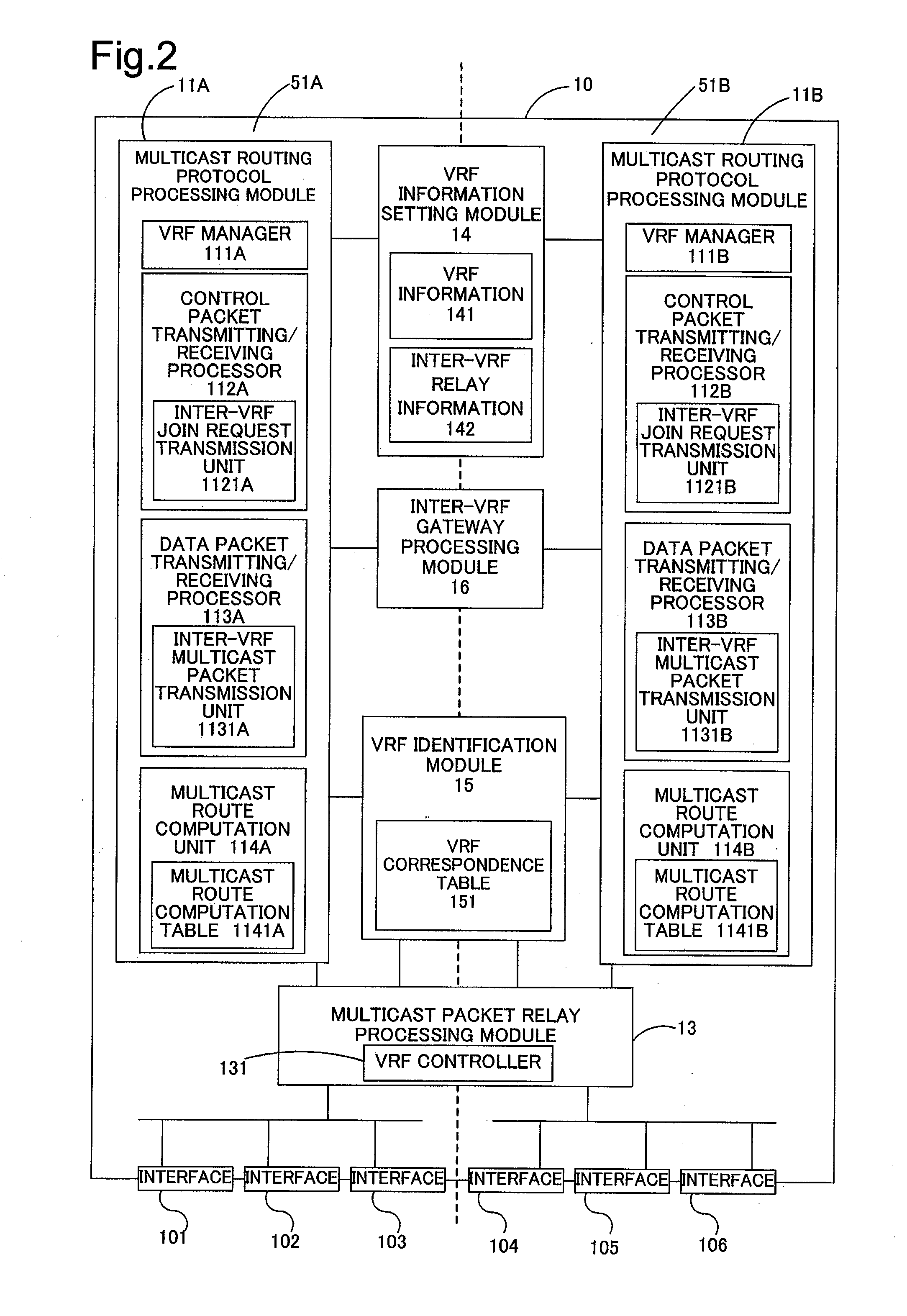
In a network relay router 10, a multicast routing protocol processing module 11A sequentially sends a join request message (CP1) to a router 30a functioning as a rendezvous point via an interface 101, based on the settings of a multicast group address or destination address and a sender VRF name. The network relay router 10 receives a multicast packet (DP1) from the router 30a via the interface 101 and acquires a sender address or source address of a transmission device SE from the received multicast packet. The network relay router 10 sends a join request message (CP2) via an interface 102 on the side of the transmission device SE and receives a multicast packet via the interface 102. This establishes an optimum multicast route (MR) between the transmission device SE and the network relay router 10.

Description

BACKGROUND[0001]The present invention relates to a multicast relay technique and specifically pertains to a multicast communication technique between logically independent networks.[0002]One known technique of simultaneously sending a packet to multiple receiving devices or receivers in a network is multicast technique where a router receives a single packet and outputs duplicates of the received packet to multiple lines. The multicast technique allows for packet transmission to multiple receiving devices as destinations by utilizing a less amount of packets, compared with the unicast technique where a transmission device or a sender sends a packet multiple times to respective destinations. The multicast technique is especially suitable for real-time multimedia communication requiring high traffic, such as streaming or teleconference.[0003]In order to allow for transmission of a multicast packet to only an authenticated user of the multicast packet, selection of an adequate line is ...

Claims


Application Information

Patent Timeline
IPC IPC(8): H04L12/56H04L12/66H04L45/16
CPCH04L12/1886H04L45/00H04L45/16
Inventor KUBO, TOSHIYUKIKADOWAKI, KEISUKEHIROTA, NAGAYUKIFUKUSHIMA, HIDEHIRO
Owner ALAXALA NETWORKS
Learn More