
System and Process of Vector Propulsion with Independent Control of Three Translation and Three Rotation Axis

a vector propulsion and independent control technology, applied in the field of system and process of vector propulsion, can solve the problems of difficult control of take off and landing, difficult control of the transition phase from horizontal to vertical flight, and never used configurations in commercial aircraft, and achieve the effect of simple independent control and complicated independent control of pitch and roll angles

Active Publication Date: 2010-12-02
RAPOSO SEVERINO
View PDF5 Cites 155 Cited by
  • Summary
  • Abstract
  • Description
  • Claims
  • Application Information

AI Technical Summary

Benefits of technology

"The present invention is a propulsion system for a vehicle that can move in a fluid or vacuum with six degrees of freedom. The system includes main thrusters and auxiliary thrusters that can be controlled independently. The main thrusters can tilt in the roll and pitch directions, and the auxiliary thrusters can also tilt in the roll direction. The vehicle also has the ability to rotate around the vertical, longitudinal, and lateral axes. The system allows for precise control of the vehicle's movement in all directions. The technical effects of this invention include improved efficiency, better stability, and reduced weight of the vehicle."

Problems solved by technology

Most of these configurations were never used in commercial aircrafts.
There is a number of reasons for the lack of success of most of the tested configurations for a VTOL aircraft, some of the reasons being: Very difficult control of take off and landing, very difficult control of the transition phase from horizontal to vertical flight, high cost and complexity, instability problems, large weight of several engines for horizontal and vertical flight and large weight of large shafts and gears, slow controls response time (aggravating instability), transmission failures, very high vibration and so on.
Among the enumeration of the problems of VTOL aircrafts it can be seen that a large portion of the problems is related to control.
Both of these configurations are not able to perform an independent control of three translation axes and three rotation axis.
It was previously mentioned that the helicopter comprises three translation axis, but in the helicopter and similar flying machines the translational displacement affects one of the rotation axis and as a result the translation displacements are not fully independent of the rotation axes.
When moving forward the conventional helicopter rotates also around the pitch axis, this meaning that the translation axis is not fully independent of the rotation axis, making it impossible for the helicopter to maintain the angle of the longitudinal axis with the horizon when moving forward or backward.
The existing patents do not cover the aforementioned problems, or just make some reference to them without proposing a feasible solution for a full vector three translational and three rotation axis control aircraft in a simple form.
In the case of spacecrafts there are solutions for this vector control, but the existing solutions are complex and demand large numbers of isolated thrusters.
However very costly because it requires the use of six equal thrusters or propellers, when actually most of the time only two will be used.
This cannot accomplish full vector three translational and three rotational axes control of the aircraft.
Patent U.S. Pat. No. 3,141,633 “TILT-WING AIRCRAFT” is a tilt wing aircraft and has a number of rotors on the wing with an additional located in the back for aircraft pitch control, it only moves the rotors in one axis, and again it cannot accomplish a full vector aircraft control.
Patent U.S. Pat. No. 3,544,042 “AERODYNE WITH VERTICAL TAKE-OFF OR LANDING MEANS” uses a similar configuration but doesn't have auxiliary propellers for additional control, therefore it cannot be full vector.

Method used


Image

  • System and Process of Vector Propulsion with Independent Control of Three Translation and Three Rotation Axis
  • System and Process of Vector Propulsion with Independent Control of Three Translation and Three Rotation Axis
  • System and Process of Vector Propulsion with Independent Control of Three Translation and Three Rotation Axis

Examples


Embodiment Construction

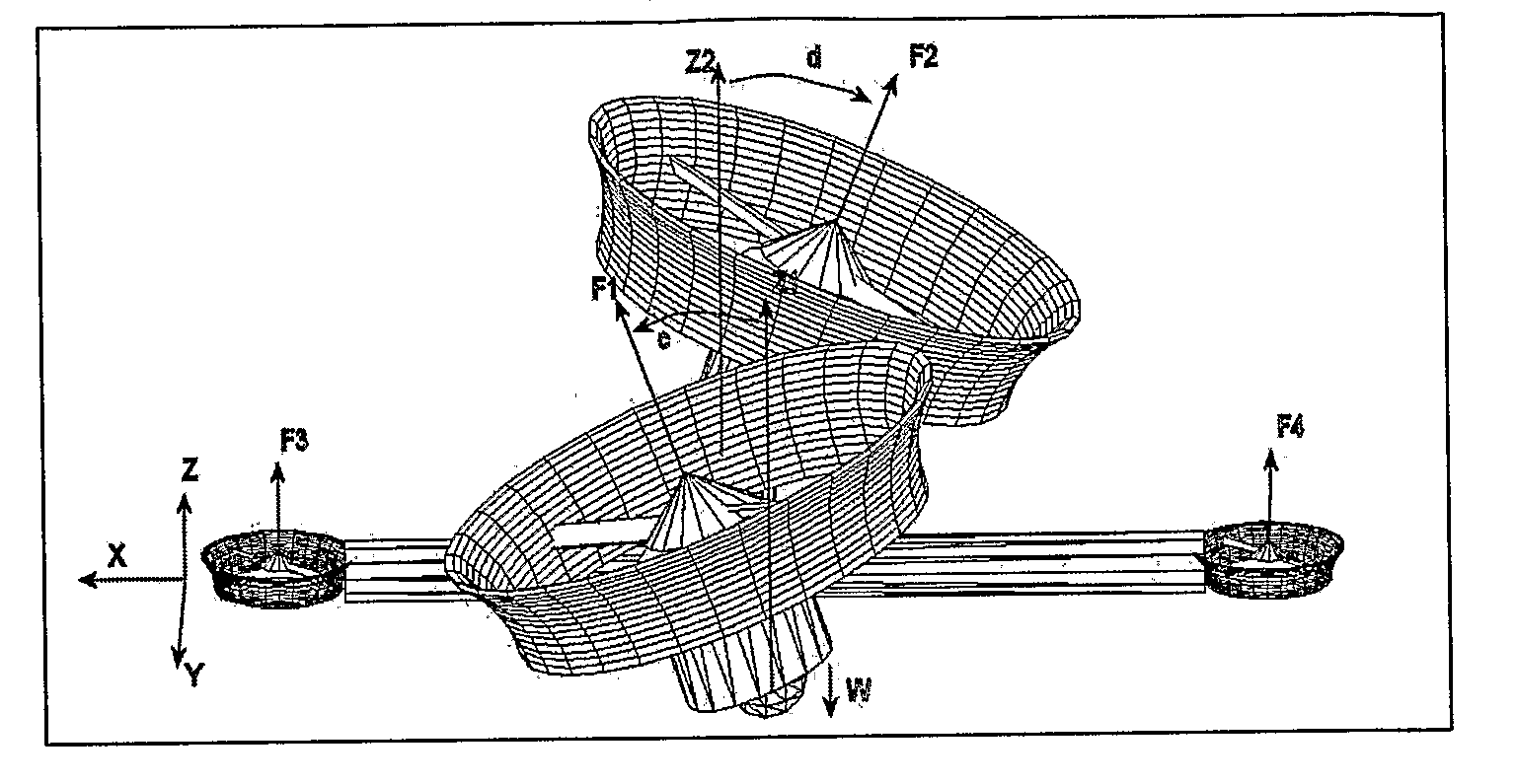
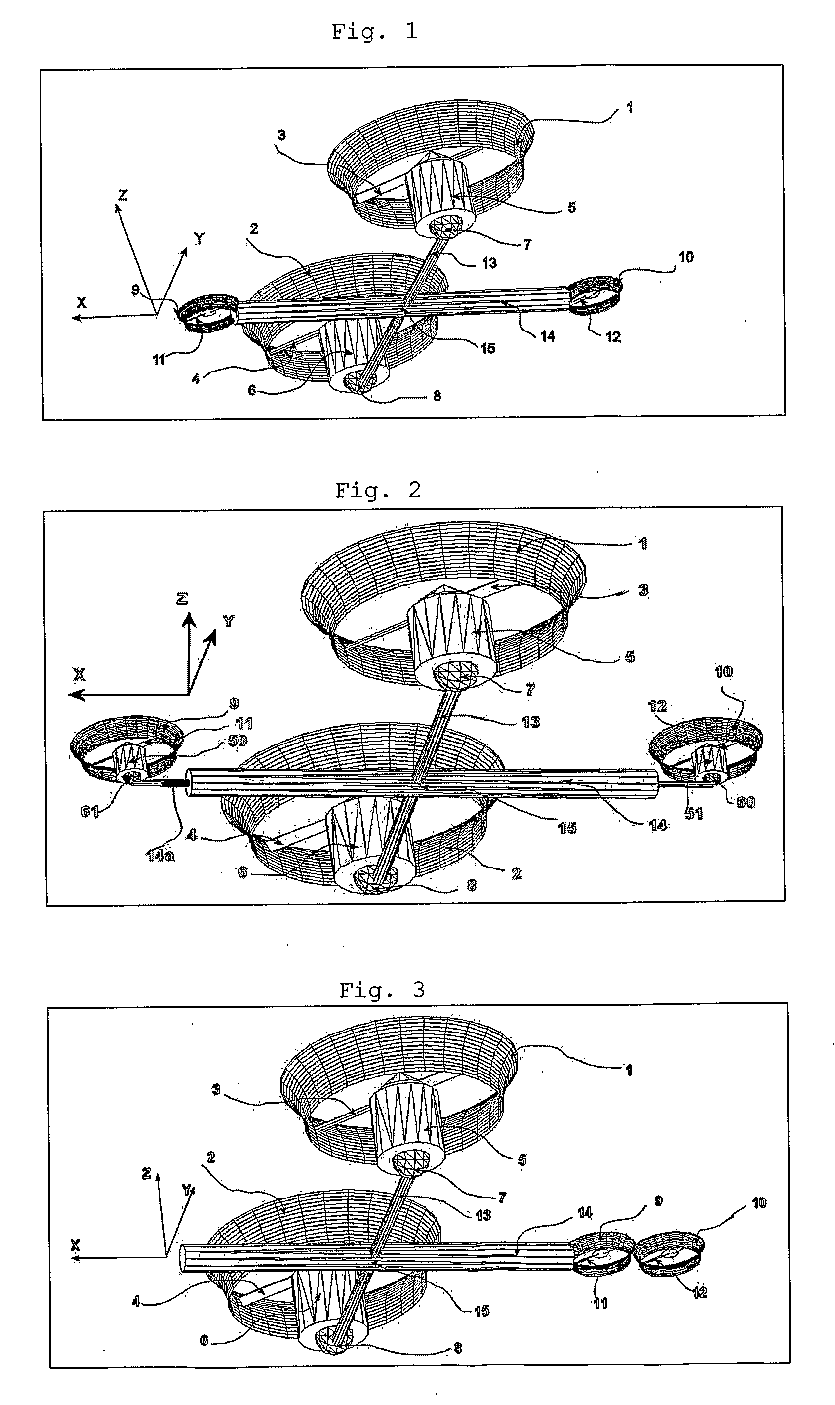
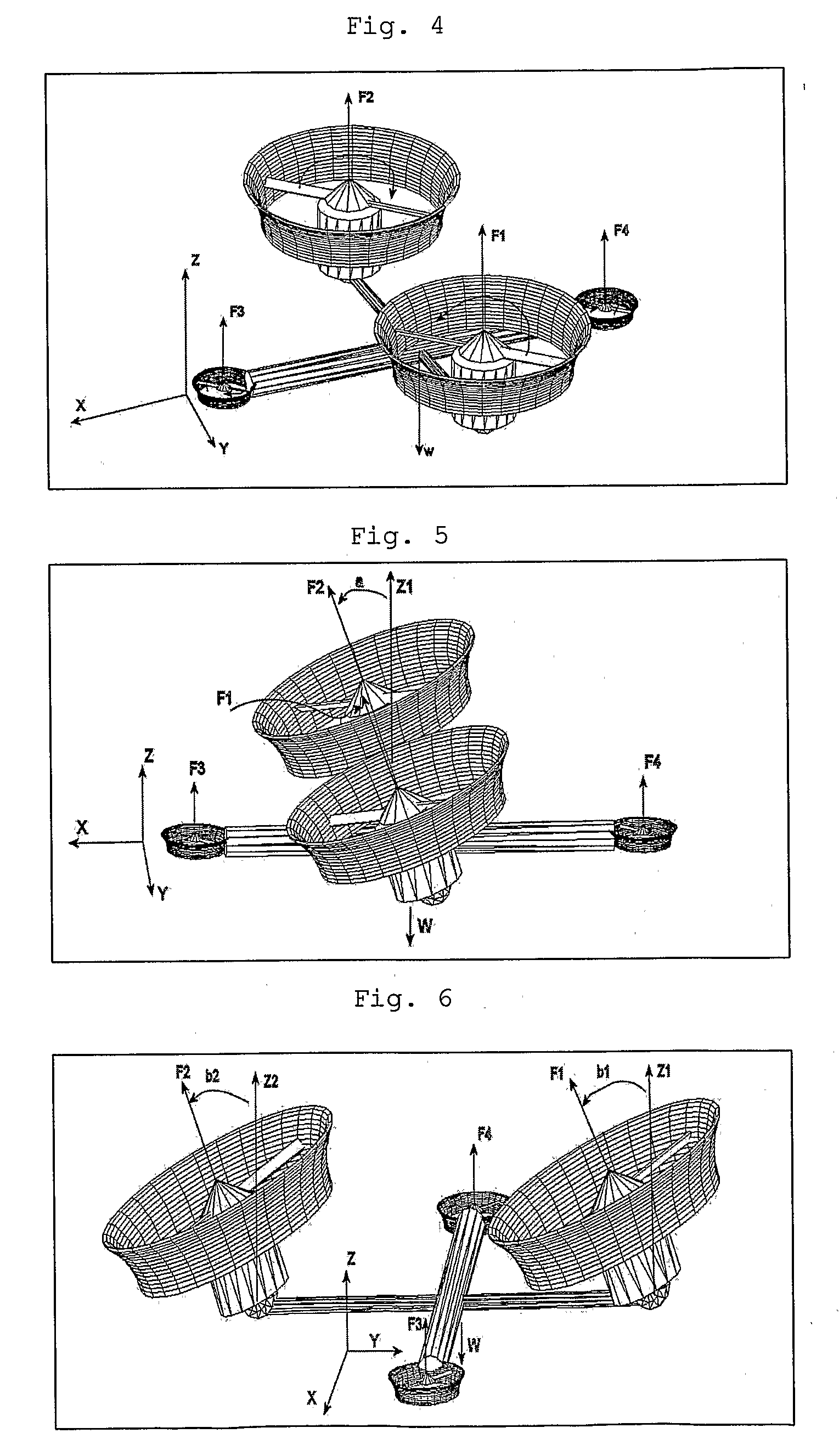
[0103]In the preferred embodiment, the present invention comprises two thrusters designated as main thrusters, that are independently moved (by any kind of engine) and are counter rotated, and which are placed laterally in the aircraft, with independent thrust variation or RPM variation or propellers pitch change (they can however be synchronized), being tiltable around two axis, positioned in such a way that their resultant thrust force, in all the possible configurations of the aircraft (take off, landing and horizontal flight), passes at or in close vicinity of the Cg, in the event of equal tilt and equal RPM or propellers pitch angle. There are also provided two thrusters or propellers (moved by any kind of engine) counter rotated, with independent control of thrust or RPM or propellers pitch change (they can however be synchronized), placed at the front and at the rear of the aircraft, these being fixed (not tiltable). In other variation of this embodiment these auxiliary thrus...


PUM


Abstract

The present invention relates to a propulsion system of a vertical takeoff and landing aircraft or vehicle moving in any fluid or vacuum and more particularly to a vector control system of the vehicle propulsion thrust allowing an independent displacement with six degrees of freedom, three degrees of translation in relation to its centre of mass and three degrees of rotation in relation to its centre of mass. The aircraft displacement ability using the propulsion system of the present invention depends on two main thrusters or propellers and which can be tilted around pitch is (I) by means of tilting mechanisms and, used to perform a forward or backward movement, can be tilted around roll axis (X) by means of tilting mechanisms and, used to perform lateral movements to the right or to the left and to perform upward or downward movements (Z), the main thrusters being further used to perform rotations around the vehicle yaw axis (Z) and around the roll is (X). The locomotion function also uses one or two auxiliary thrusters or propellers and mainly used to control the rotation around the pitch axis, these thrusters or propellers and being fixed at or near the longitudinal is of the vehicle, with there thrust perpendicular or nearly perpendicular to the roll and pitch axis of the vehicle.

Description

[0001]The present invention relates to a propulsion system for a vertical take-off and landing aircraft or vehicle capable of moving in any fluid or vacuum, more specifically it refers to a system of vector propulsion thrust control allowing independent movement with six degrees of freedom i. e. three degrees of translation in relation to its centre of mass or gravity and three degrees of rotation in relation to their centre of mass.[0002]The motion ability of the aircraft depends on two main thrusters or propellers 3 and 4 which can be tilted around the pitch axis (Y) by means of tilting mechanisms 7 and 8, used to perform a forward or backward movement, that can also be tilted around the roll axis (X) by means of tilting mechanisms 7 and 8, used to perform a right or left movement and, to perform upward or downward movement (Z) by increasing or reducing thrust, the main thrusters being further used to perform rotation around the vertical axis (Z), and around roll rotation (X). The...

Claims


Application Information

Patent Timeline
Patent Type & Authority Applications(United States)
IPC IPC(8): B64C29/00G05D1/00B64C15/12B64G1/40B63G8/08
CPCA63H23/00A63H27/00B63G8/08B63G8/16G05D1/0858B64C27/82B64C29/0033B64C2201/027B64C2201/108B64C27/20B64U10/13B64U50/18B64U10/20B64U30/10B64U30/297B64U30/26
Inventor RAPOSO, SEVERINO
Owner RAPOSO SEVERINO
Learn More