
Activation system for a robotic vehicle

Inactive Publication Date: 2010-11-25
ROBERT BOSCH GMBH
View PDF4 Cites 45 Cited by
  • Summary
  • Abstract
  • Description
  • Claims
  • Application Information

AI Technical Summary

Benefits of technology

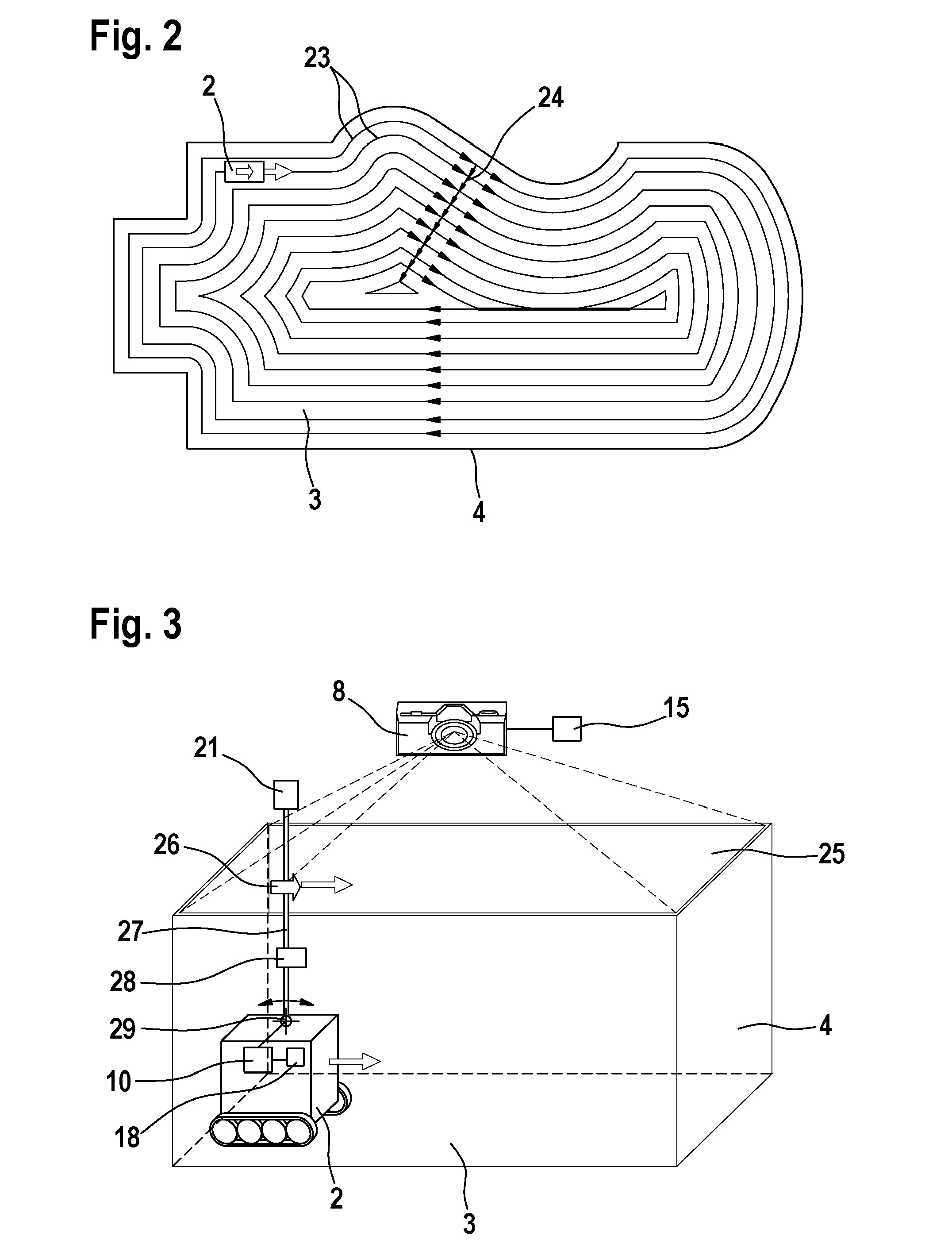
[0014]For optimizing the driving path of the robotic vehicle it is advantageous if the external logic unit detects the orientation of the robotic vehicle from the image data and considers this information when calculating the driving instructions, for example in such a way that at first a rotation takes place before the robotic vehicle is directed into a linear direction.
[0019]Preferably a bidirectional communication connection exists between the logic unit and the robotic vehicle. This embodiment enables that the robotic vehicle sends status information to the logic unit, which considers them when calculating the driving instructions. After detecting a low accumulator load status the logic unit can for example activate the robotic vehicle in such a way that it docks into a charging station. For optimizing the navigation / guiding of the robotic vehicle it is advantageous if the robotic vehicle determines odometry data and / or the environmental character with corresponding sensors, for example with the aid of IR-sensors, and transfers this data with the aid of a transmitting unit to a receiving unit that is connected with the logic unit.
[0020]In one embodiment the lawnmower can disclose the takeover of control over the driving navigation over the communication connection, for example if near-field sensors at the vehicle detect an obstacle. For increasing the data security it is advantageous to use known security mechanisms (for example communication protocols with a checksum, handshaking etc.).
[0022]One embodiment is preferred, at which the logic unit detects the position and / or orientation of the robotic vehicle only with the aid of the distinctive shape and / or color of the robotic vehicle and if necessary follows the movement. In order to optimize the position and / or orientation detection it is however advantageous to place marks at the robotic vehicle, for example LEDs in a suitable arrangement, in order to simplify the identification of the robotic vehicle and therefore the position and / or orientation determination.
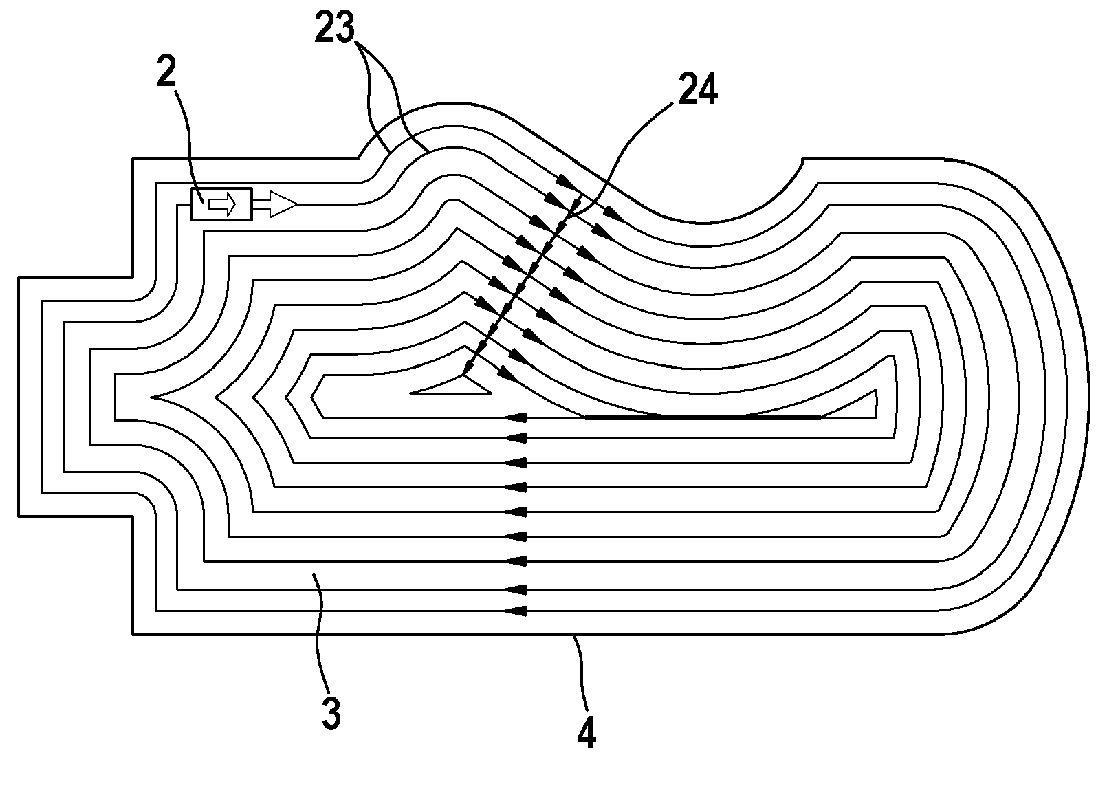
[0027]Particularly advantageous is an embodiment, at which the width of the ring track corresponds at least approximately with the width of the robotic vehicle transversely to the driving direction or the width of a working element of the robotic vehicle, for example the width of a cutting knife or a cleaning device, so that the entire work area can be completely “worked off” preferably without driving across one surface section several times.

Problems solved by technology

It is also complex to install the known activation systems and they only allow a coincidental navigation.
It is furthermore a disadvantage that the lawnmower (robotic vehicle) has a complex construction due to the provision of a logic unit for calculating the driving route and is therefore interference-prone.
A global position detection is not possible with the known activation system and therefore it is not possible to ensure that a complete mowing of the lawn takes place.
The disadvantage of these robotic vehicles is that the robotic vehicles are controlled by a sheer coincidental navigation, so that it is not possible to drive along an optimized work area path.
A complete driving along is not guaranteed for random surface and takes correspondingly long.
The programming of the path is complex and mostly requires the support of an expert.

Method used


Image

  • Activation system for a robotic vehicle
  • Activation system for a robotic vehicle
  • Activation system for a robotic vehicle

Examples


Embodiment Construction

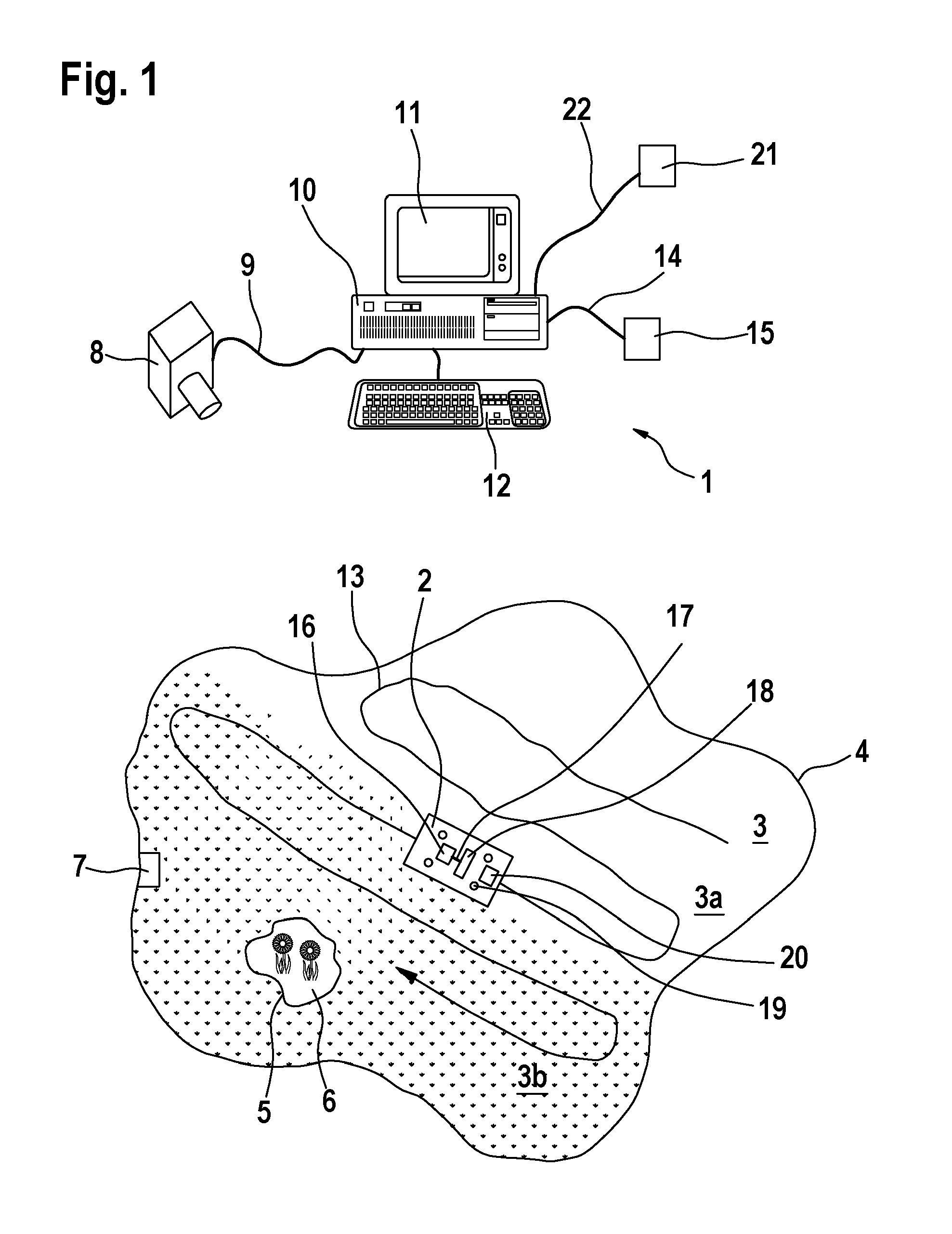
[0037]FIG. 1 schematically shows an activation system 1 for a robotic vehicle 2 that is construed as lawnmower. The robotic vehicle 2 comprises not shown drive means, in particular a drive motor and a steering device for steering the robotic vehicle 2 or two drive units, which both together create a differential drive. In the shown embodiment the drive motor is construed as electric motor, which is operated with the aid of an accumulator that is also not shown.

[0038]The robotic vehicle 2 is located on a work area 3 (lawn) with an external border 4. A static obstacle 6, in the present embodiment a flowerbed, is located within this work area 3 within an internal border 5.

[0039]A charging station 7 is located at the edges within the work area 3 for charging the accumulator of the robotic vehicle 2.

[0040]The entire work area 3 is optically detected by a camera 8, which is construed as digital video camera and which is located outside and above the work area 3. The camera 8 can for examp...


PUM


Abstract

The invention relates to an activation system (1) for a robotic vehicle (2), comprising at least one external camera (8) configured for generating image data of a work area (3) and of at least one robotic vehicle (2), and comprising at least one external logic unit (10) configured for determining the position of the at least one robotic vehicle (2) based on the image data generated by the camera (8), and comprising an external transmission unit (15, 20) configured for transmitting driving instructions, and comprising a receiving unit (16, 21) configured for receiving the driving instructions, and further comprising a controller (18) for activating drive means of at least one robotic vehicle (2) based on the driving instructions.

Description

STATE OF THE ART[0001]The invention relates to an activation system for a robotic vehicle.[0002]Activation systems are known for autonomous lawnmowers, which comprise a live conductor that is buried at the external border of the work area (lawn). Corresponding sensors on the lawnmower detect if the external border is driven over and as a result a control unit causes a turning maneuver of the lawnmower. It is also complex to install the known activation systems and they only allow a coincidental navigation. Marker-based lawnmower robotic vehicles are for example described in EP 55 04 73 B1 and U.S. Pat. No. 6,984, 952 B2.[0003]An improved activation system for autonomous lawnmowers is known from GB 2 277 152 A1. The known activation system comprises a number of landmarks, which are distanced from each other and which border a work area (lawn). The autonomous lawnmower communicates actively with the landmarks in order to determine its position and to calculate a driving route based on...

Claims


Application Information

Patent Timeline
IPC IPC(8): G05D1/00
CPCG05D1/0225G05D1/0242G05D2201/0208G05D1/0272G05D1/0246E04H4/1654
Inventor BENZLER, ULRICH-LORENZEMARX, KLAUSCARSTENS-BEHRENS, SOENKENIEHSEN, WOLFGANGKOEDER, THILOKOCH, CHRISTOPHBROSCHE, THOMASPLATZER, JOACHIM
Owner ROBERT BOSCH GMBH
Learn More