Liquid crystal display device

a liquid crystal display and display screen technology, applied in non-linear optics, instruments, optics, etc., can solve the problems of ordinarily difficult manufacture of reverse wavelength dispersion retardation films, and achieve the effects of preventing contrast ratio drops, wide viewing angle range, and high contrast ratio

Active Publication Date: 2010-11-25
SHARP KK
View PDF21 Cites 11 Cited by
  • Summary
  • Abstract
  • Description
  • Claims
  • Application Information

AI Technical Summary

Benefits of technology

[0015]As a result of various research on LCD devices having a high contrast ratio and being free of coloring over a wide viewing angle range, by tackling the above-described problems (1) and (2), the inventors found that coloring at an oblique viewing angle can be suppressed by using a reverse wavelength dispersion-type biaxial retardation film having low retardation, by compensating the retardation exhibited by LC cell constituent materials other than the LC layer (for instance, color filter layer, transparent electrode materials such as ITO). Thus, the inventors focused on the retardation of the retardation films and the retardation of the LC cell, and found that coloring at an oblique viewing angle can be sufficiently suppressed even when using reverse wavelength dispersion-type biaxial retardation films, having comparatively lower retardation than in conventional cases, by optimizing the retardation of the retardation films at the wavelength 450 nm, the wavelength 550 nm and the wavelength 650 nm, and by optimizing the thickness-direction retardation of the LC cell at the wavelength 450 nm, the wavelength 550 nm and the wavelength 650 nm. The inventors arrived at the present invention on the basis of the above finding, which allows solving the above-described problems.
[0028]The above retardation film is a reverse wavelength dispersion-type biaxial retardation film whose in-plane slow axis is orthogonal, in a plan view of the display surface, to the absorption axis of a polarizer that is on the same side with respect to the LC cell, and such that the retardation film satisfies equations (1) to (4) above. Such a configuration allows optimizing retardation conditions not only for green light around the wavelength 550 nm, but also for blue light around the wavelength 450 nm and red light around the wavelength 650 nm, and allows providing a high-contrast ratio, high-quality LCD device that is free of coloring during black display, over a wide viewing angle range. The LCD device of the present invention is not limited to an embodiment in which the in-plane slow axis of the retardation film is perfectly orthogonal, in a plan view of the display surface, to the absorption axis of the polarizer on the same side with respect to the LC cell. So long as a high contrast ratio can be obtained in the front direction, the angle formed by the in-plane slow axis of the retardation film and the absorption axis of the polarizer on the same side with respect to the LC cell, in a plan view of the display surface, may deviate from 90° by about ±1° (more preferably ±0.5°. Blue coloring may occur during black display when R0(B) / R0(G) and / or Rth(B) / Rth(G) exceed 0.965. Also, red coloring may occur during black display when R0(R) / R0(G) and / or Rth(R) / Rth(G) are smaller than 1.015.
[0032]The above LCD device may have a first polarizer; a first retardation film; an LC cell; a second retardation film; and a second polarizer having an absorption axis azimuth that is orthogonal, in a plan view of the display surface, to that of the first polarizer, in this order, wherein the first retardation film is a reverse wavelength dispersion-type biaxial retardation film whose in-plane slow axis is orthogonal, in a plan view of the display surface, to the absorption axis of the first polarizer, and such that the first retardation film satisfies equations (1) to (4) above, and wherein the second retardation film is a reverse wavelength dispersion-type biaxial retardation film whose in-plane slow axis is orthogonal, in a plan view of the display surface, to the absorption axis of the second polarizer, and such that the second retardation film satisfies equations (1) to (4) above. Such a configuration allows preventing contrast ratio drops in the front direction, and allows realizing a high contrast ratio, free of coloring, over a wide viewing angle range.
[0038]In the above LCD device, preferably, at least one of the thicknesses d(R), d(G) and d(B) of the LC layer, corresponding to regions where the blue, green and red color filter layers are respectively provided, is different from the others of the thicknesses d(R), d(G) and d(B); more preferably, d(R), d(G) and d(B) are different from each other. Such configurations allow realizing easily an LC cell that satisfies equations (5) and (6) above.
[0039]The present invention allows realizing an LCD device having a high contrast ratio, and free of coloring during black display, over a wide viewing angle range.BEST MODES FOR CARRYING OUT THE INVENTION

Problems solved by technology

In Patent Document 5, however, the in-plane retardation |Rxy(550)| at the wavelength 550 nm that is required in each retardation layer is substantial, and hence there remains room for improvement in that the manufacture of such reverse wavelength dispersion retardation films is ordinarily difficult, since, intrinsically, reverse wavelength dispersion retardation films do not elicit retardation.

Method used


Image

  • Liquid crystal display device
  • Liquid crystal display device
  • Liquid crystal display device

Examples


first embodiment

of the Present Invention

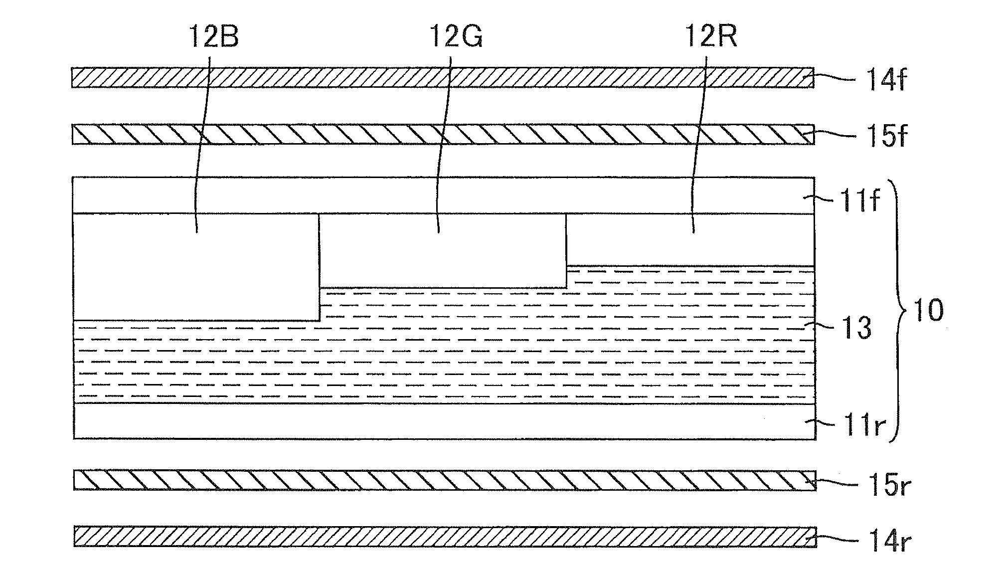
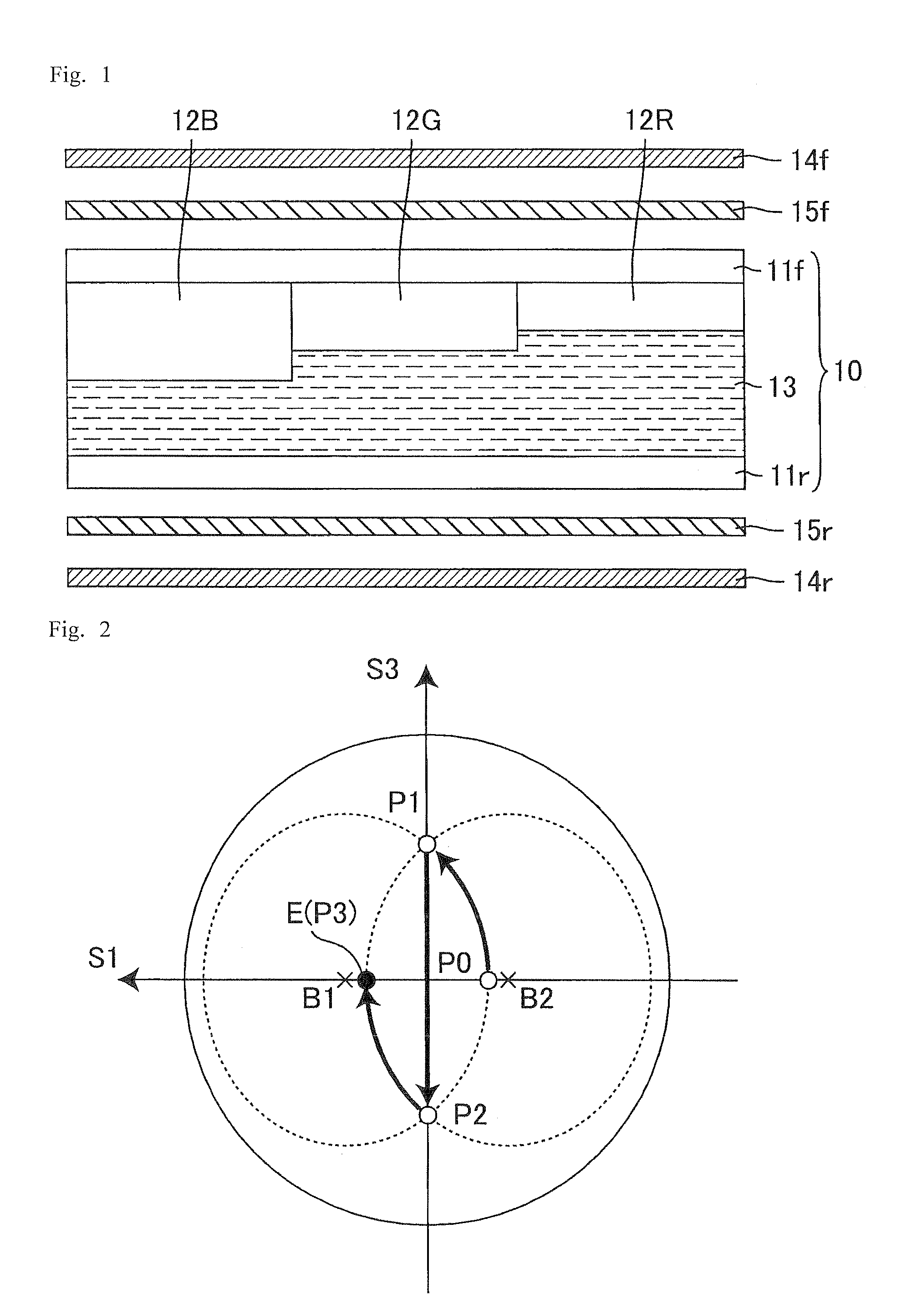
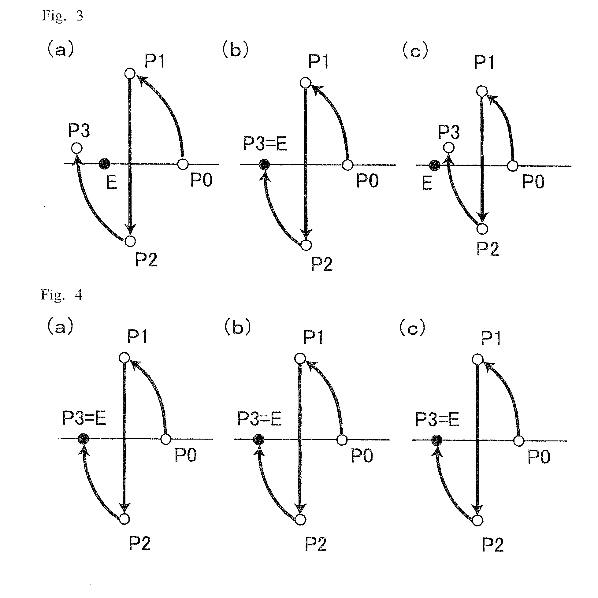
[0041]A first embodiment of the LCD device in which the present invention is used will be explained with reference to FIGS. 1 to 4. FIG. 1 is a cross-sectional schematic diagram illustrating the configuration of an LCD device of a first embodiment of the present invention. FIG. 2 is a diagram for explaining the transition of polarization states in the LCD device of the first embodiment of the present invention, and illustrates a S1-S3 plane in the Poincare sphere. FIG. 3 is a diagram for explaining the transition of polarization states in a conventional LCD device, wherein (a) illustrates an instance of wavelength 450 nm, (b) an instance of wavelength 550 nm, and (c) an instance of wavelength 650 nm. FIG. 4 is a diagram for explaining the transition of polarization states in the LCD device of the first embodiment of the present invention, wherein (a) illustrates an instance of wavelength 450 nm, (b) an instance of wavelength 550 nm, and (c) an instance of wav...

second embodiment

of the Present Invention

[0064]A second embodiment of the LCD device in which the present invention is used will be explained with reference to FIGS. 5 to 7. FIG. 5 is a cross-sectional schematic diagram illustrating the configuration of an LCD device of a second embodiment of the present invention. FIG. 6 is a diagram for explaining the transition of polarization states in the LCD device of the second embodiment of the present invention, and illustrates a S1-S3 plane in the Poincare sphere. FIG. 7 is a diagram for explaining the transition of polarization states in the LCD device of the second embodiment of the present invention, wherein (a) illustrates an instance of wavelength 450 nm, (b) an instance of wavelength 550 nm, and (c) an instance of wavelength 650 nm.

[0065]As illustrated in FIG. 5, the LCD device of the present invention includes a VA LC cell 20; a pair of polarizers 24f, 24r disposed so as to sandwich the LC cell 20; a biaxial retardation film 25r disposed between the...

example 1

[0078]Example 1 corresponds to the actual manufacture of an LCD device identical to that of the first embodiment of the present invention. Table 1 summarizes the various optical parameters (retardations and wavelength dispersions thereof) of the LCD device, together with those of Example 2.


PUM


Abstract

The present invention provides a liquid crystal display device having a high contrast ratio and no coloring during black display, over a wide viewing angle range. The liquid crystal display device of the present invention includes a reverse wavelength dispersion-type biaxial retardation film having R0(B) / R0(G) and Rth(B) / Rth(G) not greater than 0.965 and R0(R) / R0(G) and Rth(R) / Rth(G) not smaller than 1.015; and a vertical alignment liquid crystal cell that has a blue, a green, and a red color filter layer and that satisfies Rth_LC(B) / Rth_LC(G)≦1.000 and Rth_LC(R) / Rth_LC(G)≧1.000. R0(B), R0(G) and R0(R) denote the in-plane retardations of the retardation film at wavelengths 450 nm, 550 nm and 650 nm. Rth(B), Rth(G) and Rth(R), and Rth_LC(B), Rth_LC(G) and Rth_LC(R) respectively denote the thickness-direction retardations of the retardation film and the liquid crystal cell at wavelengths 450 nm, 550 nm and 650 nm.

Description

TECHNICAL FIELD[0001]The present invention relates to a liquid crystal display (LCD) device. More particularly, the present invention relates to an LCD device suitable for LCD devices that have an optimally designed wavelength dispersion characteristic of a liquid crystal (LC) cell and a retardation film.BACKGROUND ART[0002]LCD devices are widely used as display devices in computers, televisions and other information processing devices. In particular, LCDs of TFT type (hereinafter also referred to as “TFT-LCDs”) are widely used and their market is expected to keep on growing, with an accompanying demand for ever greater image quality. The explanation below deals with a TFT-LCD example, but the present invention is not limited to TFT-LCDs, and is also applicable to passive matrix type LCDs, plasma-address LCDs and the like, and is generally applicable to all LCDs that perform display on the basis of an LC that is sandwiched between a pair of substrates having respective electrodes fo...

Claims


Application Information

Patent Timeline
IPC IPC(8): G02F1/1335
CPCG02F1/133371G02F2413/12G02F1/133634G02F1/133514
Inventor SAKAI, AKIRAHASEGAWA, MASSAHIRONINOMIYA, IKUO
Owner SHARP KK
Why Eureka
Try Eureka