
Safety barriers

a safety barrier and fence technology, applied in the field of safety barriers, can solve the problems of reducing affecting the safety of workers, so as to achieve simple and cost-effective manufacturing, small spacing, and simple and relatively fast installation

Inactive Publication Date: 2010-11-25
PRESTON JOHN CLEMENT
View PDF2 Cites 13 Cited by
  • Summary
  • Abstract
  • Description
  • Claims
  • Application Information

AI Technical Summary

Benefits of technology

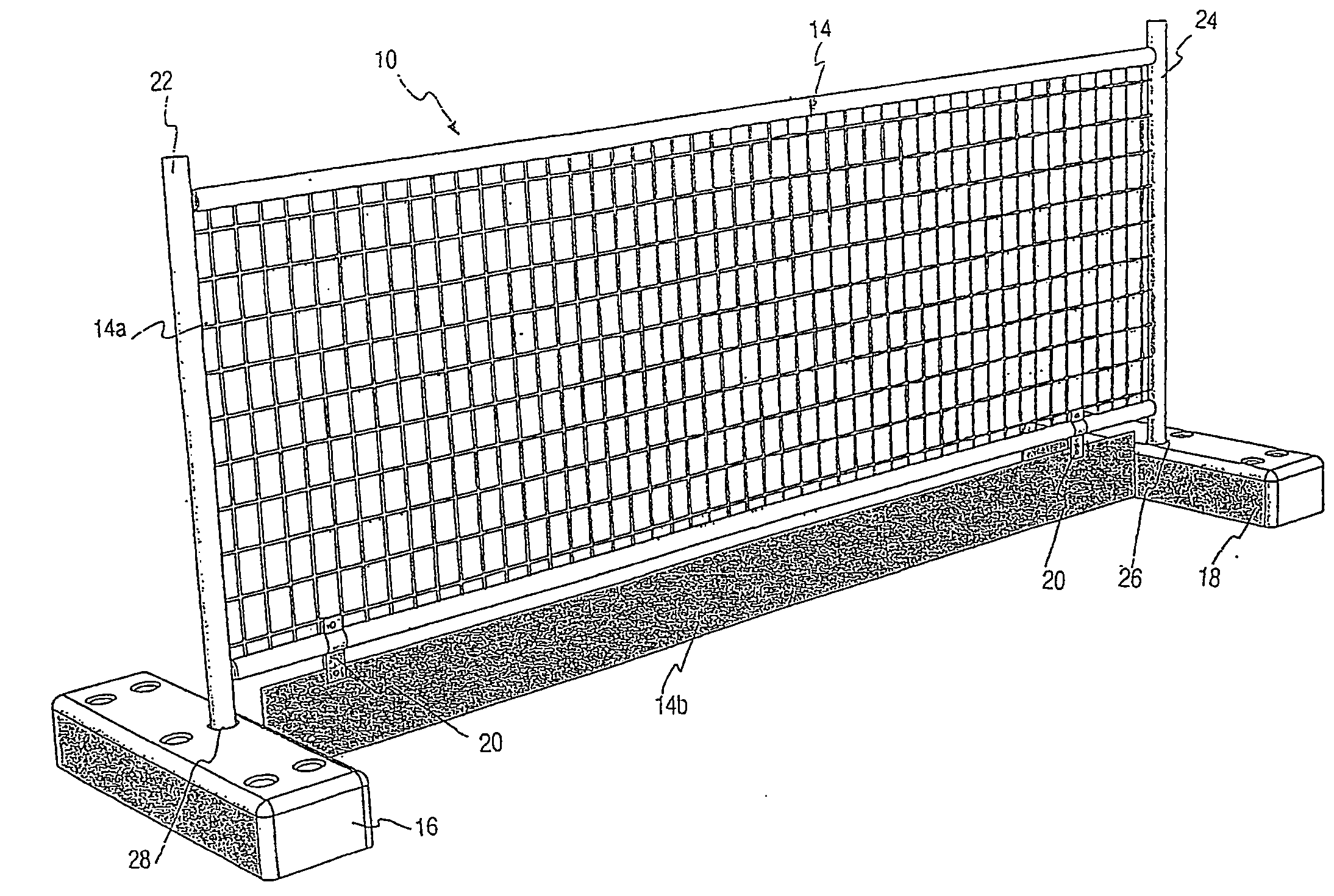
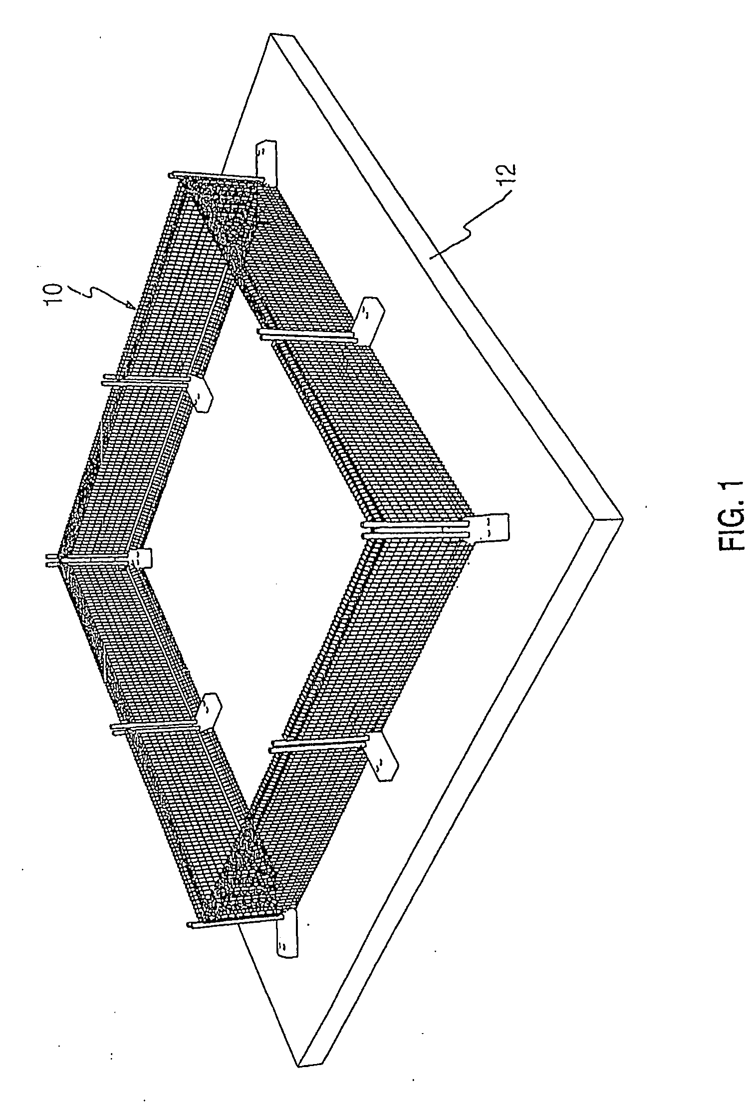
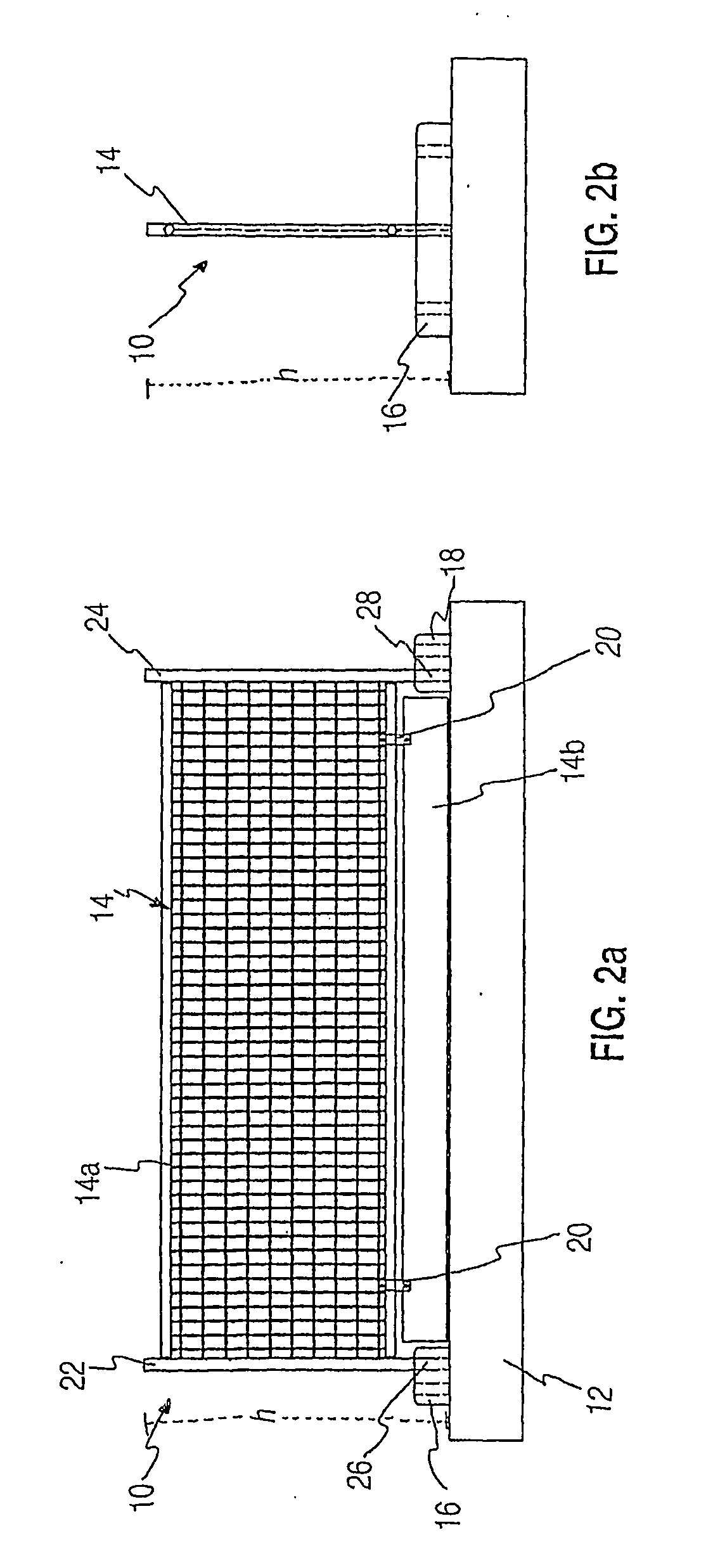
The present invention provides a safety barrier module for use in erecting a fenced-off zone around the perimeter of a building floor during construction. The module includes a barrier panel and a counterweighted footing block for supporting the panel in an upright position. The barrier panel has a geometrically shaped recess for accommodating the footing block. The module can be easily installed and is adaptable for different construction needs. The invention also provides a kickboard for attachment to the safety barrier module and a method for securing the building floor. The technical effects of the invention include improved safety and protection during construction, reduced labor costs, and efficient use of space.

Problems solved by technology

In the building industry, it is known to erect safety barriers around the perimeter of floors of a multi-story building during construction in order to protect workers and objects from falling to the ground below, thereby averting dangerous and hazardous situations.
Bolting the fences to the floors involves significant labour, and is time consuming, as it is necessary to drill into the concrete floor of the building, and then position the fences in the desired locations and apply the bolts.
This process is again time consuming, involves significant labour, and is thus expensive.
Clamping the fence sections to the floors also involves substantial labour and time.
It also creates a potentially hazardous situation for workers since they will be located adjacent the edge of the building when applying the clamps to the perimeter edge of the floor and installing the fences.
Given the time and labour involved in erecting bolted or clamped fences, it has been known for workers to attempt to install such fences hastily and incorrectly, by not applying all of the required bolts for example, and / or incorrectly drilling the concrete floor, and / or incorrectly installing the concrete bolt, resulting in a faulty installation and causing a potentially dangerous situation.

Method used


Image

  • Safety barriers
  • Safety barriers
  • Safety barriers

Examples


second embodiment

[0073]FIG. 5 shows a safety barrier module 40 with an alternative form of barrier panel 44. The second panel section 44b of the barrier panel 44 includes a rectangular solid metal sheet with elongate tubular sections 46 surrounding three sides. The second panel section 44b is attached to the first panel section 44a by screwing the outer elongate tubular sections 46a to the lower tubular section 42 of the first panel section 44a. Alternatively, the second panel section 44b may be welded to the first panel section 44a to provide a more permanent attachment means.

third embodiment

[0074]FIGS. 6 and 7 show a safety barrier module 50, shown from the front and rear of the module 50 respectively, with yet another alternative form of barrier panel 52. In this embodiment, the barrier panel 52 extends from a predetermined height down to substantially the floor (not shown) as one integral wire mesh web or sheet which is geometrically shaped. As such, there is no requirement for two distinct first and second panel sections. Rather, the barrier panel 52 has corner “cut outs”, marked by reference 54, in the lower edge to provide inward stepped recesses to accommodate the footing blocks 56, 58.

[0075]The upper and lower edges of the wire mesh barrier panel 52 are bent over, primarily for safety reasons, but also for additional strength. At the lower edge, a solid rectangular metal panel 53 is fixed inside the folded over barrier panel 52 to minimise small articles from passing through the perforations in the barrier panel 52.

[0076]A plurality of safety barrier modules 50 ...


PUM

PropertyMeasurementUnit
spacing distanceaaaaaaaaaa

Abstract

The present invention relates to safety barriers, and in particular, for use around the perimeter of building floors during construction of a building. In one form, the present invention provides a safety barrier module for use in erecting a fenced-off zone around the perimeter of a building floor during construction of a building, the safety barrier module including: a barrier panel for inhibiting the passage of workers or objects from the building floor to the ground below; and at least one counterweighted footing block for receiving a support post connected to the barrier panel, the footing block arranged to rest on the building floor and to counteract loads and forces on the barrier panel to support the barrier panel in a substantially upright position relative to the building floor; wherein the barrier panel is geometrically shaped to extend from a predetermined height down to substantially the building floor level.

Description

FIELD OF THE INVENTION[0001]The present invention relates to safety barriers. In particular, the invention was conceived for use around the perimeter of building floors during construction of a building.BACKGROUND TO THE INVENTION[0002]Safety barriers find use in varied applications where an open space is to be fenced-off or access to and from restricted or unsafe areas is to be prevented. In the building industry, it is known to erect safety barriers around the perimeter of floors of a multi-story building during construction in order to protect workers and objects from falling to the ground below, thereby averting dangerous and hazardous situations.[0003]Such safety barriers typically include a plurality of fencing modules or panels which are temporarily bolted or clamped around the perimeter of each floor of the building. These modules include a panel section which sits substantially perpendicular to the floor of the building, fastened between support poles using bolts or clamps....

Claims


Application Information

Patent Timeline
Patent Type & Authority Applications(United States)
IPC IPC(8): E04H17/16E04H17/14B23P17/04
CPCE01F13/022Y10T29/49826E04G2005/148E04G21/3233E04G21/3238E04G21/32E04H17/04E04H17/06
Inventor PRESTON, JOHN CLEMENT
Owner PRESTON JOHN CLEMENT
Learn More