
One-piece vented piston

a vented piston and piston body technology, applied in the field of pistons, can solve the problems of affecting the accuracy with which metered quantities of substances can be dispensed, adverse effects on the shelf life of stored substances, and evaporation of ingredients from the substances to be stored, and achieve the effect of effective removal of air and simple construction

Active Publication Date: 2010-11-25
3M INNOVATIVE PROPERTIES CO
View PDF48 Cites 8 Cited by
  • Summary
  • Abstract
  • Description
  • Claims
  • Application Information

AI Technical Summary

Benefits of technology

[0007]The present invention is concerned with the provision of a vented piston assembly, suitable for use in storage and dispensing systems, which is of comparatively simple construction but capable of ensuring the effective removal of air from a substance that is being stored within the system.
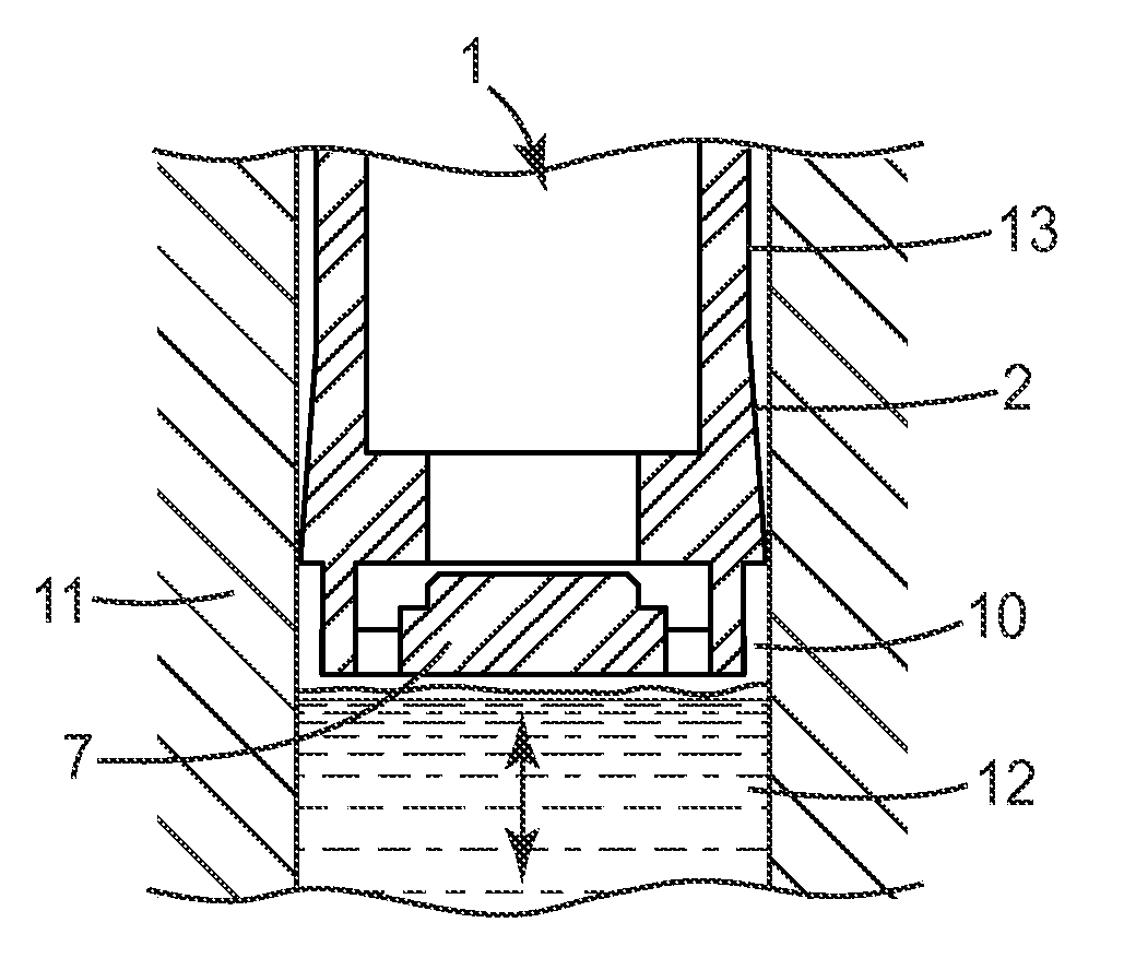
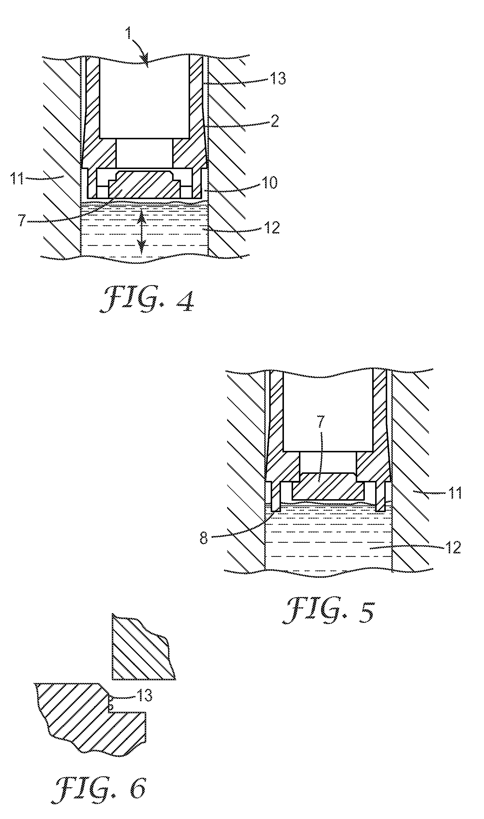
[0009]When used in a storage chamber of a dispensing system, a piston in accordance with the invention can be used to allow air to escape from within the chamber as the plunger is inserted. The air-removal process terminates when the cap moves into the closed position, which may occur, for example, when the plunger has contacted a substance in the storage chamber and the cap moves into the closed position under the resulting pressure on the front side of the plunger. The closed position of the cap may then be maintained, for example by continued pressure on the front side of the plunger or because the cap is a tight fit in the venting passage. The plunger may be provided, at its periphery, with sealing means that engages the wall of the storage chamber to seal the front side of the plunger from the rear side. The sealing means may also function to maintain the position of the plunger in the storage chamber following movement of the cap into the closed position. In a dispensing system of that type, the substance may be loaded into the storage chamber before the piston is inserted. This may facilitate access to the storage chamber and enable filling times to be optimized.
[0012]In a piston in accordance with the invention, the cap may be resiliently biased towards the open position by a spring. Advantageously, the spring is formed as a one-piece moulded component together with the cap and at least a part of the plunger. This enables the piston to be manufactured in a comparatively simple and cost-effective manner.
[0013]In an embodiment of the invention, the spring extends at least partially around the cap. The length of the spring may thereby be substantially greater than the distance traveled by the cap in moving between the open and closed positions. This may be of advantage particularly in a piston of comparatively small dimensions such as those used in dental cartridges in that it can enable the cap to respond to comparatively low forces, and to respond readily to changes in pressure exerted on its front side. It can also assist, when the piston is used in the storage chamber of a dispensing system, in ensuring that the cap remains in the closed position while a substance is being stored in the chamber following the removal of air therefrom.
[0014]The plunger of the piston assembly is advantageously hollow, providing a buffer space that can be used, if required, to compensate for variable filling of a storage system in which the piston assembly is employed. This may be of utility in the particular case of dental cartridges that are filled by an automated process, when the small size of the storage chambers within the cartridges (typically in the range of from 100 to 500 mm3) may give rise to comparatively high filling tolerances (in the range, for example, of from 10 to 20%). A hollow piston also offers access for a setting tool, inserted into the plunger from the rear side thereof to engage the cap and control its movement into the closed position. The setting tool may, for example, be used to hold the cap in the open position, or to pull it into the closed position.

Problems solved by technology

A problem that is frequently encountered when filling a substance into a dispensing system in which it is intended to be stored is that of removing air from the storage chamber and ensuring that no voids or air bubbles are trapped in the stored substance.
The presence of air may have an adverse effect on the shelf life of the stored substance, and the presence of voids or air bubbles may have an adverse effect on the accuracy with which metered quantities of the substance can be dispensed.
One conventional way of addressing this problem is to assemble the dispensing system under vacuum but this can result in the evaporation of ingredients from the substance to be stored and a consequent alteration in its composition.
Another way of addressing the problem is to fill the system through its dispensing outlet but this method can only be used with systems that are appropriately configured.

Method used


Image

  • One-piece vented piston
  • One-piece vented piston
  • One-piece vented piston

Examples


Embodiment Construction

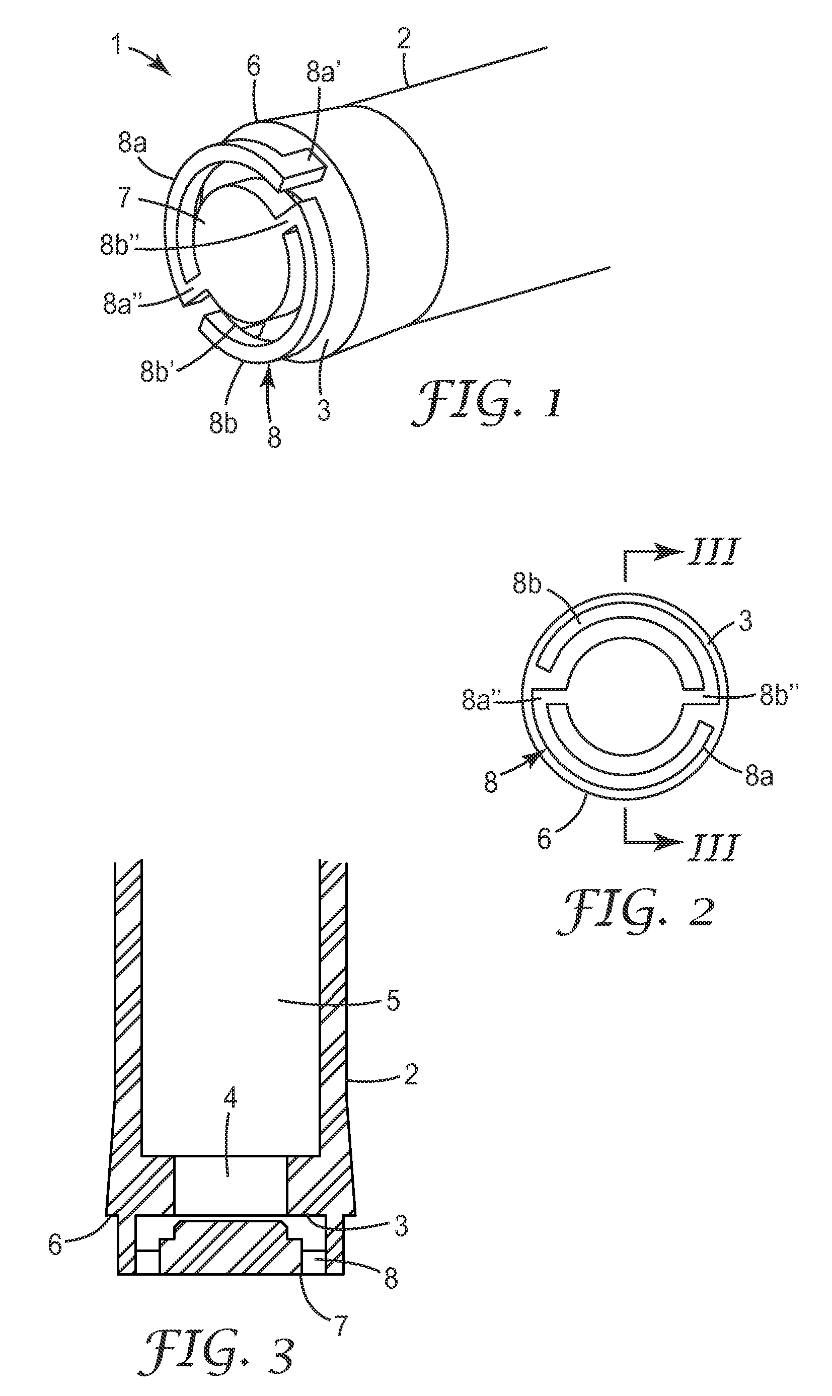
[0029]FIGS. 1 to 3 show a vented piston 1 suitable for use in a storage chamber of a dispensing cartridge (not shown) that will be described below. The assembly 1 comprises a hollow plunger 2 having a front end wall 3 through which extends a venting passage 4 providing a connection between the front side and the rear side of the plunger. The interior of the plunger 2 forms a passageway 5, which extends from the front end of the plunger to its rear end (not shown). Externally, the plunger 2 is flared outwards slightly at its front end to form a sealing lip 6, the purpose of which will be described below.

[0030]The piston 1 further comprises a cap 7 positioned adjacent the front side of the front end wall 3 of the plunger 2 and connected to the front end wall by a spring 8 (described in greater detail below). The cap 7 is shaped to seat on the front end wall 3 and close the venting passage 4, but is resiliently-biased by the spring 8 into the open position shown in FIGS. 1 to 3, in whi...


PUM


Abstract

A vented piston (1) comprises a plunger (2) having a front side and a rear side, a venting passage (4) extending between the front side and the rear side, and a cap (7) located adjacent the front side. The cap is resiliently-biased by a spring (8) towards an open position in which air can pass through the venting passage from the front to the rear side of the plunger, and is movable from the open position into a closed position in which the cap closes the venting passage. The piston may be used in a storage chamber (10) of a dispensing system whereby air can be removed from the storage chamber by moving the plunger in the direction of a substance (12) stored in the chamber.

Description

CROSS-REFERENCE TO RELATED APPLICATIONS[0001]This application claims priority to United Kingdom Patent Application No. 0721774.8, filed Nov. 7, 2007.FIELD OF THE INVENTION[0002]The present invention relates to pistons of the type that enable air to be vented from a chamber in which the piston is located.BACKGROUND OF THE INVENTION[0003]The invention is concerned, more especially, with pistons suitable for use in dispensing systems that also function to store a substance to be dispensed until it is required for use. Dispensing systems of that type are known, for example, in the field of dentistry where dental materials such as impression materials, restoration materials and filler materials are often supplied in cartridges comprising a storage chamber in which the material, or a component thereof, is contained. Such a cartridge may be provided, at its front end, with a sealed dispensing outlet and, at its rear end, with a piston that closes the storage chamber. When the dental materi...

Claims


Application Information

Patent Timeline
Patent Type & Authority Applications(United States)
IPC IPC(8): G01F11/00F01B31/00A61C5/62
CPCA61C5/062A61C5/068B65D2205/04B05C17/01B65D83/0005B05C17/00579A61C5/62A61C5/68
Inventor BOEHM, ANDREAS J.
Owner 3M INNOVATIVE PROPERTIES CO
Learn More