
Midfoot insert construction

a technology of inserts and midfoot, which is applied in the field of insert construction of midfoot, can solve the problems of instability of the foot, limiting flexibility, and rigid outsoles not suitable for every spor

Active Publication Date: 2010-11-25
NIKE INC
View PDF100 Cites 98 Cited by
  • Summary
  • Abstract
  • Description
  • Claims
  • Application Information

AI Technical Summary

Benefits of technology

The invention is a shoe for dancing that has a flexible sole. The sole has a pivot portion and a plurality of flex grooves that allow for bending and flexibility. The flex grooves are arranged in a radial pattern and can be set to different depths to achieve different levels of flexibility. The shoe also has sole pods that provide continuous traction on the floor and can be separated by flex grooves. The flex grooves are designed to facilitate bending in different directions. The shoe can be used for both ballet and tap dancing.

Problems solved by technology

In addition, the periphery of a sole surrounding the pivot does not contact the ground in a uniform manner, which can lead to instability of the foot.
The rigid outsole, while limiting flexibility, prevents undulations in and / or debris disposed on a playing surface from causing injury to a user's foot by preventing such undulations and / or debris from applying a force through the outsole to the user's foot.
While a relatively rigid outsole provides a benefit to a user during a particular sport such as baseball, football, or soccer, such a rigid outsole is not suitable for every sport.
While such flexibility may provide some degree of flexibility about a longitudinal axis of the user's foot, such rotation is typically prevented or restricted to limit the amount of roll experienced by a user's foot during running to provide the foot with proper support.
Conventional articles of footwear do not typically permit a user's foot to flex about a longitudinal axis of the foot, as described above.

Method used


Image

  • Midfoot insert construction
  • Midfoot insert construction
  • Midfoot insert construction

Examples


Embodiment Construction

[0065]Example embodiments will now be described more fully with reference to the accompanying drawings. Example embodiments are provided so that this disclosure will be thorough, and will fully convey the scope to those who are skilled in the art. Numerous specific details are set forth such as examples of specific components, devices, and methods, to provide a thorough understanding of embodiments of the present disclosure. It will be apparent to those skilled in the art that specific details need not be employed, that example embodiments may be embodied in many different forms and that neither should be construed to limit the scope of the disclosure. In some example embodiments, well-known processes, well-known device structures, and well-known technologies are not described in detail.

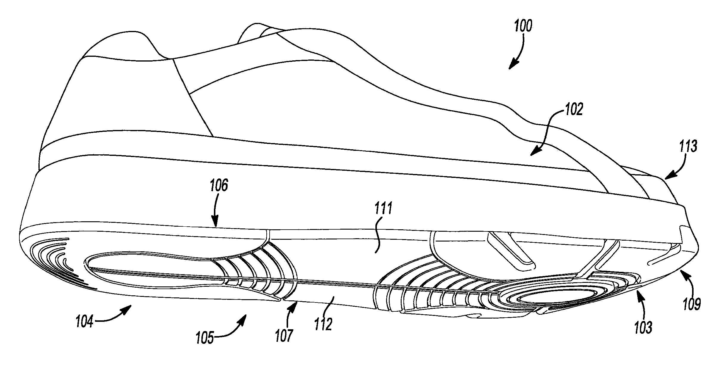
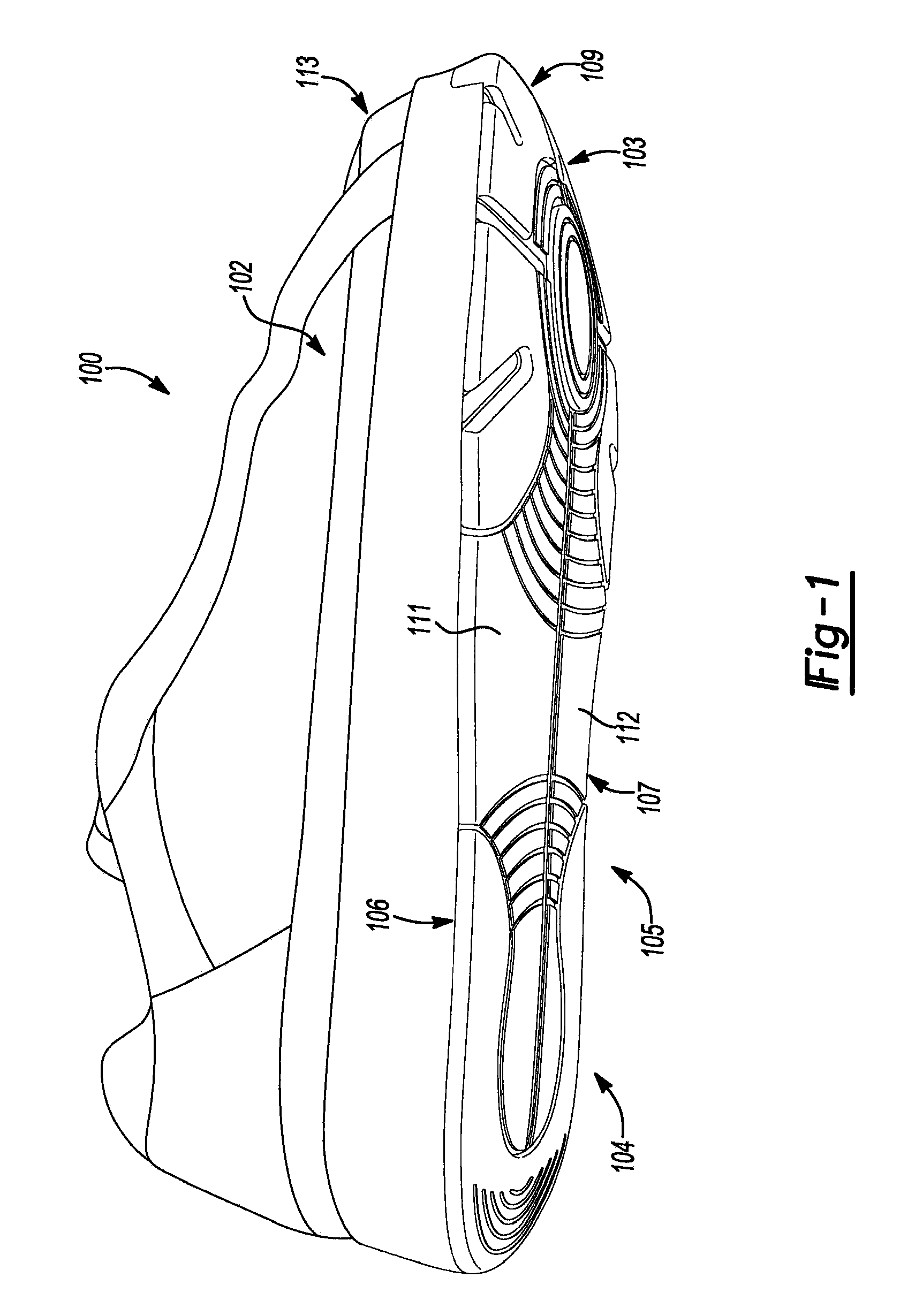
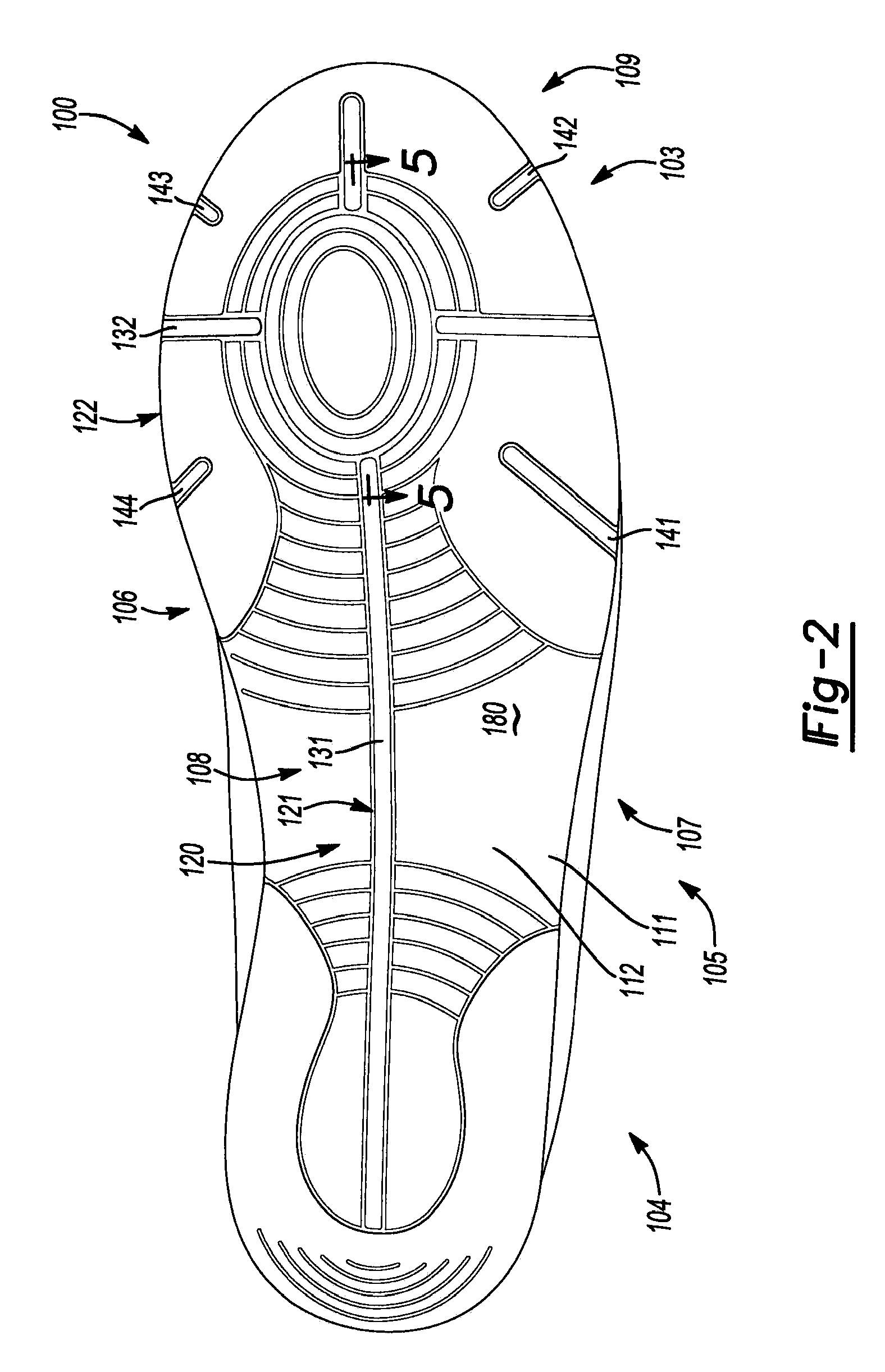
[0066]FIGS. 1 and 2 illustrate an embodiment of article of footwear 100. In particular, FIG. 1 is an isometric view of an embodiment of article of footwear 100 and FIG. 2 is a bottom view of an embod...


PUM

PropertyMeasurementUnit
distanceaaaaaaaaaa
distanceaaaaaaaaaa
volumeaaaaaaaaaa

Abstract

An article of footwear is provided and includes an outsole structure having a forefoot portion, a heel portion, and a midfoot portion disposed between the forefoot portion and the heel portion. The midfoot portion includes a series of ribs cooperating to define a series of pockets disposed between the forefoot portion and the heel portion. The plurality of pockets include a smaller volume proximate to a longitudinal axis extending through a center of the outsole structure and a greater volume proximate to an outboard, lateral edge and an outboard, medial edge of the article of footwear.

Description

CROSS-REFERENCE TO RELATED APPLICATION[0001]This application is a continuation-in-part of U.S. patent application Ser. No. 12 / 419,671 filed on Apr. 7, 2009, which claims the benefit of U.S. Provisional Patent Application No. 61 / 103,922 filed on Oct. 8, 2008. The entire disclosures of each of the above applications are incorporated herein by reference.FIELD[0002]The present disclosure relates to an article of footwear, and in particular, to an article of footwear incorporating flex grooves and / or a midfoot insert providing the article of footwear with increased flexibility.BACKGROUND[0003]This section provides background information related to the present disclosure which is not necessarily prior art.[0004]Articles of footwear configured for pivoting have been previously proposed. These articles typically include a pivot disposed on a ball portion of a foot. In addition, the periphery of a sole surrounding the pivot does not contact the ground in a uniform manner, which can lead to i...

Claims


Application Information

Patent Timeline
Patent Type & Authority Applications(United States)
IPC IPC(8): A43B13/14
CPCA43B3/0042A43B3/0052A43B5/12A43B7/142A43B13/181A43B13/141A43B13/16A43B13/223A43B7/143
Inventor FERRIGAN, TIMOTHY S.FORESTA, BRIANGRASER, PATRICIA J.SAITO, CHRISTINE L.
Owner NIKE INC
Learn More