
Method and System for Finite Impulse Response (FIR) Digital Filtering

a digital filtering and finite impulse technology, applied in the field of finite impulse response (fir) digital filtering, can solve the problems of linear increase of computation cost, high computation cost for long convolutions, and unsuitability for real-time filtering of direct time domain convolutions

Active Publication Date: 2010-11-18
TEXAS INSTR INC
View PDF4 Cites 28 Cited by
  • Summary
  • Abstract
  • Description
  • Claims
  • Application Information

AI Technical Summary

Problems solved by technology

While there is no inherent latency in direct time domain convolution, the computational cost may be high for long convolutions as the computation cost increases linearly with the length of the filter.
Thus, direct time domain convolution may be unsuitable for real-time filtering.
The computational cost of these techniques increase logarithmically with the length of the filter, rather than linearly.
However, these techniques have an inherent input to output latency equal to the length of the block as the input sample block must be full before beginning computation.
Thus, single-block convolution may also be unsuitable for real-time filtering due to the high latency.

Method used


Image

  • Method and System for Finite Impulse Response (FIR) Digital Filtering
  • Method and System for Finite Impulse Response (FIR) Digital Filtering
  • Method and System for Finite Impulse Response (FIR) Digital Filtering

Examples


Embodiment Construction

[0014]Specific embodiments of the invention will now be described in detail with reference to the accompanying figures. Like elements in the various figures are denoted by like reference numerals for consistency.

[0015]Certain terms are used throughout the following description and the claims to refer to particular system components. As one skilled in the art will appreciate, components in digital systems may be referred to by different names and / or may be combined in ways not shown herein without departing from the described functionality. This document does not intend to distinguish between components that differ in name but not function. In the following discussion and in the claims, the terms “including” and “comprising” are used in an open-ended fashion, and thus should be interpreted to mean “including, but not limited to . . . .” Also, the term “couple” and derivatives thereof are intended to mean an indirect, direct, optical, and / or wireless electrical connection. Thus, if a ...


PUM


Abstract

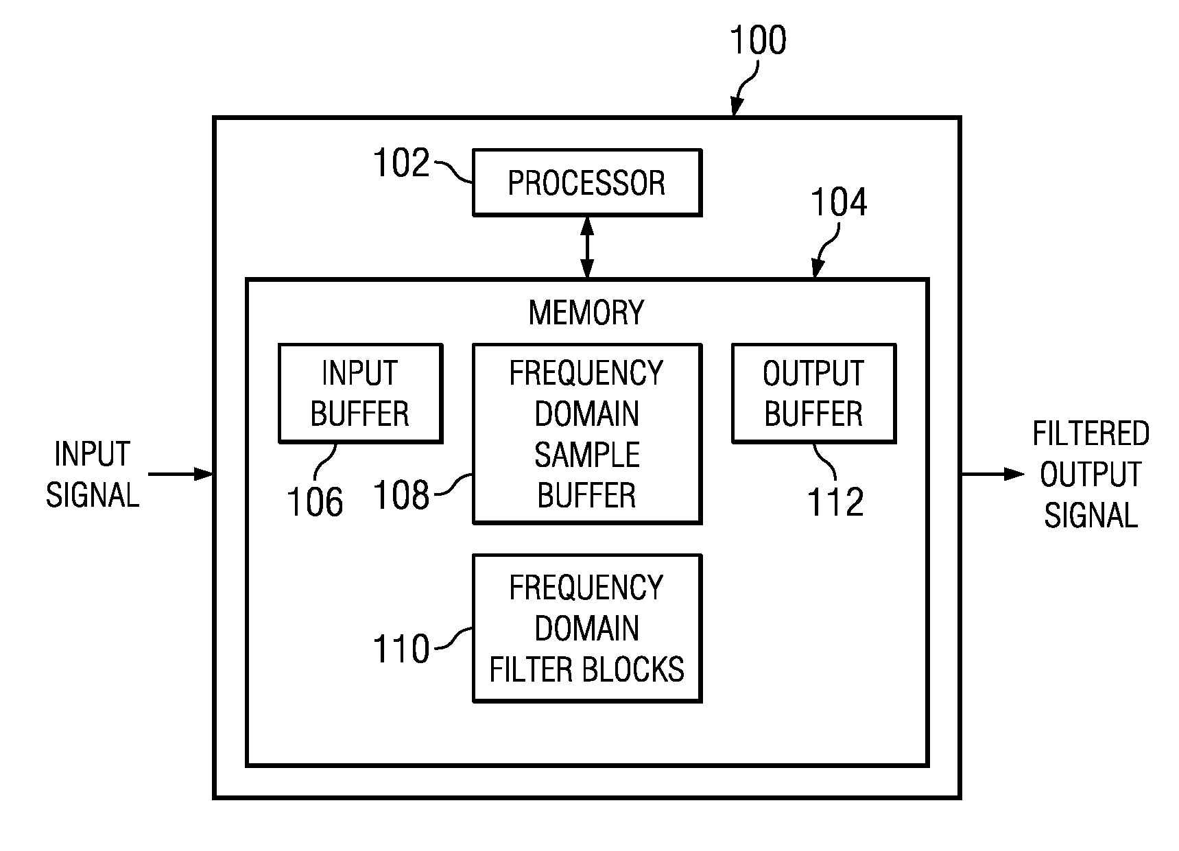
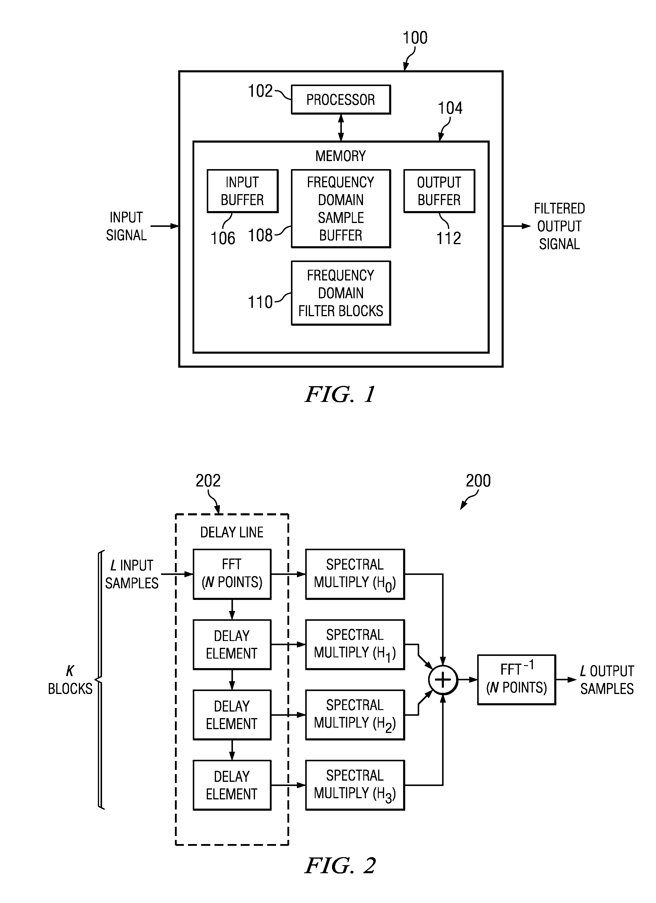
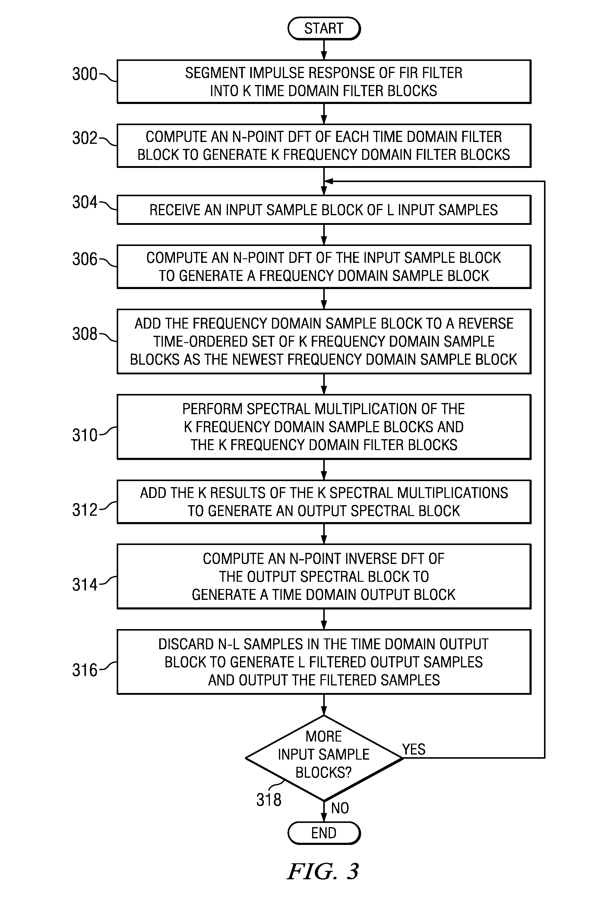
A method for finite impulse response (FIR) digital filtering is provided that includes generating a frequency domain sample block from an input sample block of length L, adding the computed frequency domain sample block to a reverse time-ordered set of previously generated frequency domain sample blocks as a newest frequency domain sample block, computing a spectral multiplication of each of K newest frequency domain sample blocks in the reverse time-ordered set with a corresponding frequency domain filter block in a time-ordered set of K frequency domain filter blocks of a FIR filter, adding the K results of the K spectral multiplications to generate an output spectral block, inverse transforming the output spectral block to generate a time domain output block, and outputting L filtered output samples from the time domain output block.

Description

CROSS-REFERENCE TO RELATED APPLICATIONS[0001]This application claims benefit of U.S. Provisional Patent Application Ser. No. 61 / 178,554, filed May 15, 2009, which is incorporated herein by reference in its entirety.BACKGROUND OF THE INVENTION[0002]Digital filters are often important components of audio and video processing systems. One type of digital filter often used in such systems is a finite impulse response (FIR) filter. A typical FIR filter is a linear-phase filter that delays the input signal without distorting the phase of the input signal. The delay on the input signal may be implemented as a set of memory elements, i.e., a delay line, that store the delayed elements of the FIR calculation.[0003]In general, a FIR filter operates by convolving the input signal with the impulse response, i.e., the set of coefficients, of the filter. In implementation, different techniques may be used to perform the convolution such as, for example, direct time domain convolution, single-bloc...

Claims


Application Information

Patent Timeline
Patent Type & Authority Applications(United States)
IPC IPC(8): G06F17/17G06F17/14
CPCG06F17/156H03H17/06H03H17/0213
Inventor LONGLEY, LESTER ANDERSON
Owner TEXAS INSTR INC
Learn More