
Fuel cell system

a fuel cell and system technology, applied in the direction of battery/fuel cell control arrangement, electrochemical generators, transportation and packaging, etc., can solve the problems of a prolonged period of time or a non-optimized next system activation

Active Publication Date: 2010-11-18
TOYOTA JIDOSHA KK
View PDF5 Cites 25 Cited by
  • Summary
  • Abstract
  • Description
  • Claims
  • Application Information

AI Technical Summary

Benefits of technology

[0006]An object of the present invention is to provide a fuel cell system capable of reducing the period of time required to stop the fuel cell system and suppressing freezing of a fuel cell.Means for Solving the Problems
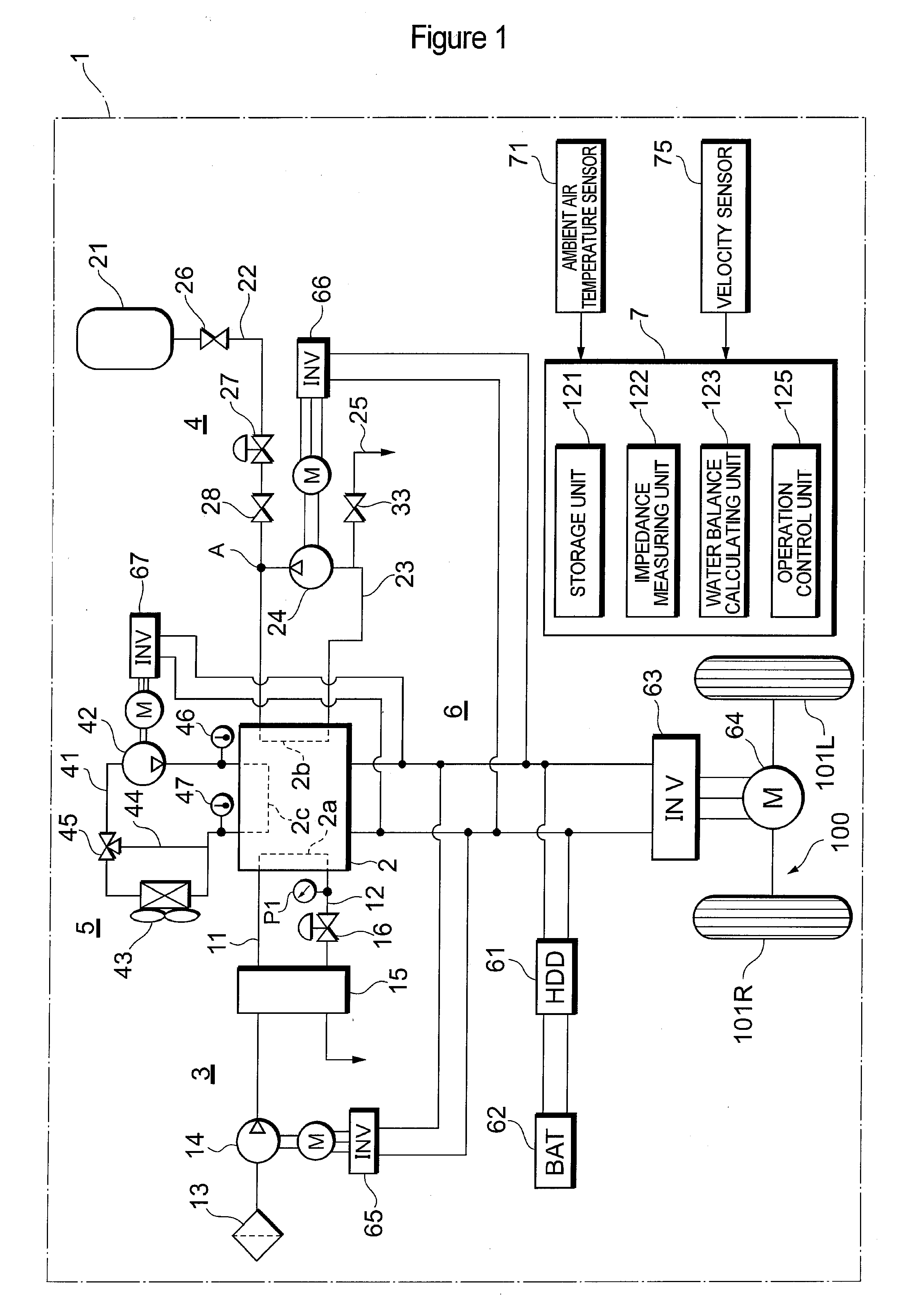
[0105]As described above, according to the eighth control example, when the impedance cannot be measured during the dry operation and the measured value cannot be normally updated, the dry operation is prohibited and the fuel cell 2 is restored to the normal operation. Consequently, the prohibition of the dry operation can suppress the risk of excessive drying (a so-called dry-up) of the fuel cell 2 which exists when the dry operation is performed in a state where it is unclear whether the ion-exchange membrane of the fuel cell 2 is rather dry or rather wet. Therefore, even without having to estimate the water content of the fuel cell 2 when the impedance cannot be measured as is the case with the sixth control example, the fuel cell 2 can be operated in an appropriate state and fail-safe can be achieved.

Problems solved by technology

The proton-exchange membrane fuel cell is operated at approximately 60 to 80 degrees C. However, there may be cases where the fuel cell is used in sub-freezing environments.
When the fuel cell is left in a shutdown state in a sub-freezing environment, the water content (generated water or water vapor) inside the fuel cell could freeze until a next system activation and, as a result, the next system activation could end up not being preferably performed or could take a prolonged period of time.

Method used


Image

  • Fuel cell system
  • Fuel cell system
  • Fuel cell system

Examples


first control example

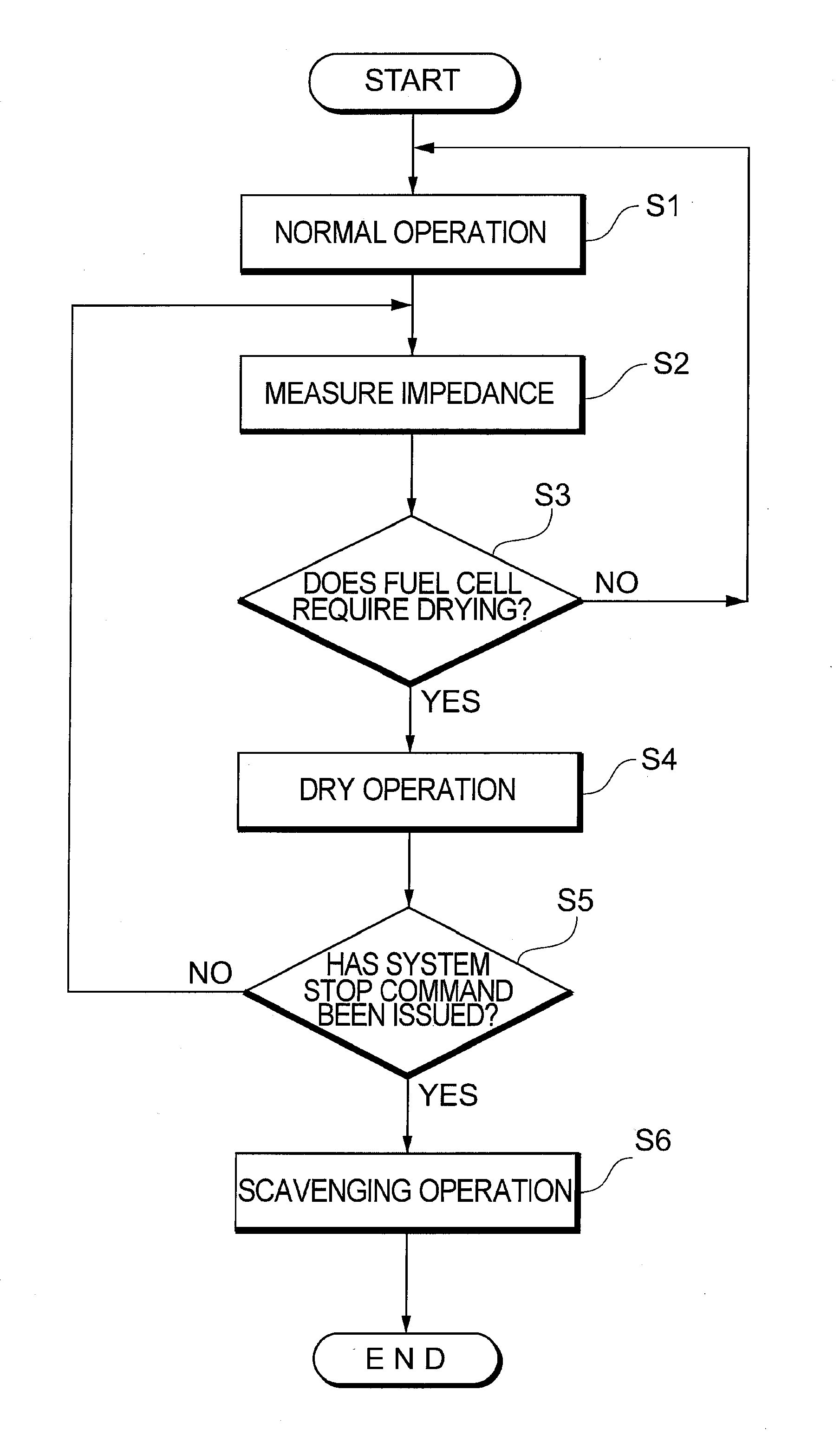
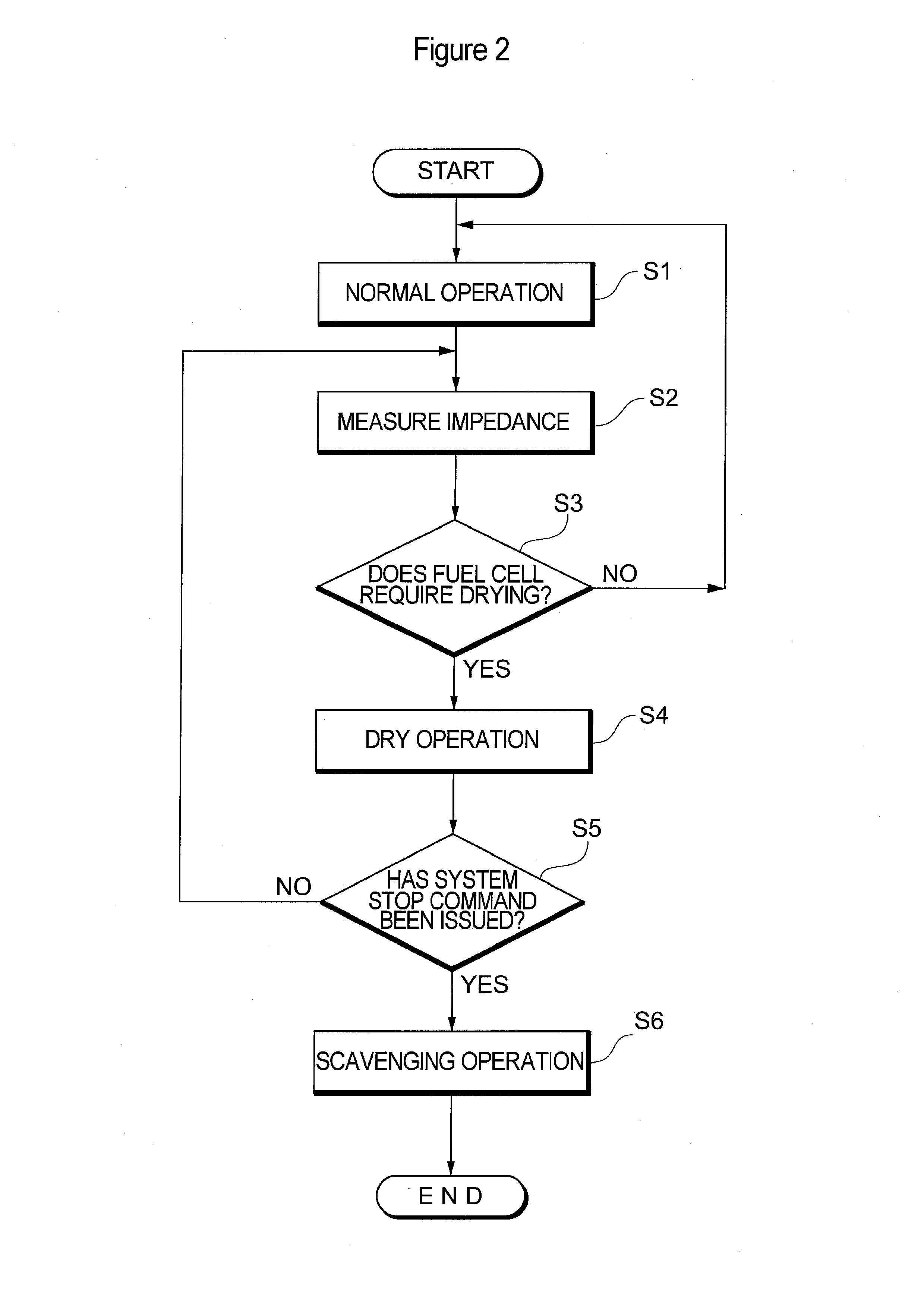
[0050]As illustrated in FIG. 2, first, the fuel cell system 1 is executing a normal operation of the fuel cell 2 (step S1). In this case, in the normal operation, the fuel cell 2 is operated (electric power is generated) in a state where an air stoichiometric ratio is set equal to or greater than 1.0 (theoretical value) so as to suppress power loss and obtain a high generating efficiency. An air stoichiometric ratio refers to an excess oxygen rate indicating how much supplied oxygen is in excess with respect to a just proportion of oxygen for reacting with hydrogen.

[0051]Next, during a normal operation, the impedance of the fuel cell 2 is measured by the impedance measuring unit 122 (step S2). Based on the measured impedance, a present water content of the fuel cell 2 is estimated as a state quantity of the fuel cell 2 in operation. The estimation is performed using, for example, a map indicating a correlative relationship between impedance and water content. The map is to be stored...

second control example

[0061]Next, a second control example will be described with reference to FIG. 3. The difference from the first control example is that steps S14 and S15 have been added. Since steps S11 to S13 and S16 to S18 are the same as steps S1 to S6 in FIG. 2, descriptions thereof will be omitted.

[0062]In step S14, the controller 7 determines whether or not the impedance measured value in step S12 is significantly deviated from an impedance target value. In this case, the impedance target value refers to a target value for operating the fuel cell 2 in the dry condition and which is stored in the storage unit 121.

[0063]When the difference between the impedance measured value and the impedance target value is equal to or greater than a threshold (step S14: Yes), the dry operation is executed while raising the degree of dryness of the fuel cell 2 in stages (step S15). For example, the supply flow rate of oxidation gas is increased in stages up to a target value thereof. On the other hand, when th...

third control example

[0065]Next, a third control example will be described with reference to FIG. 4. A difference from the first control example is that an attempt is made to resolve departures due to an operation in the dry condition in conformance to the circumstances. Therefore, in the third control example, required output determination (step S25) and wetness control (step S26) are added to the first control example. Since steps S21 to S24 and S27 to S28 are the same as steps S1 to S6 in FIG. 2, descriptions thereof will be omitted.

[0066]During the execution of the dry operation (step S24), the controller 7 determines whether or not the required output of the fuel cell 2 is equal to or greater than a threshold (step S25). The “threshold” can be set to, for example, half of a maximum output of the fuel cell 2 or an output that enables the vehicle 100 to travel at 60 km per hour. Although a criterion of determination has been set to a required output of the fuel cell 2, a rate of increase of the requi...


PUM

PropertyMeasurementUnit
humidityaaaaaaaaaa
velocityaaaaaaaaaa
velocityaaaaaaaaaa

Abstract

An object of the present invention is to reduce the period of time required to stop a fuel cell system and to suppress freezing of a fuel cell. The fuel cell system includes a controller that controls operations of a fuel cell, and the controller operates the fuel cell in a dry condition according to a state quantity (e.g., impedance) of the fuel cell in operation. The controller can operate the fuel cell in a dry condition before a system stop command is issued. In addition, the controller can switch an operation of the fuel cell from a dry condition to a wet condition when a required output of the fuel cell or a vehicle speed of a vehicle equals or exceeds a predetermined value.

Description

TECHNICAL FIELD[0001]The present invention relates to a fuel cell system including a fuel cell, and in particular, to water content control of a fuel cell in operation.BACKGROUND ART[0002]In a fuel cell system, a fuel gas typified by hydrogen gas and an oxidation gas typified by air are supplied to a fuel cell. The fuel cell generates power by a power-generating reaction between the fuel gas and the oxidation gas, and generates water on an air electrode-side. With a proton-exchange membrane fuel cell, an electrolyte membrane is responsible for the conduction of protons during the reaction between the fuel gas and the oxidation gas. Therefore, in order to efficiently maintain the power-generating reaction, a moisture condition of the electrolyte membrane must be monitored and controlled at an appropriate state.[0003]The proton-exchange membrane fuel cell is operated at approximately 60 to 80 degrees C. However, there may be cases where the fuel cell is used in sub-freezing environmen...

Claims


Application Information

Patent Timeline
Patent Type & Authority Applications(United States)
IPC IPC(8): H01M8/04
CPCB60L11/1887B60L11/1892B60L11/1894H01M8/04253H01M8/04291Y02E60/50H01M8/04626H01M8/04649H01M8/04828H01M2008/1095Y02T90/34H01M8/04529B60L58/33B60L58/34B60L58/40Y02T10/70Y02T90/40
Inventor ASO, SHINJIKAJIWARA, SHIGETOTSUCHIYA, NAOHISA
Owner TOYOTA JIDOSHA KK
Learn More