
Self-compensating hydrostatic planar bearing device and the method thereof

a technology of hydrostatic planar bearing and self-compensation, which is applied in the direction of bearings, lines, bearings, etc., can solve the problems of hydrostatic bearings in the hydrostatic slide system that cannot time delay of their reaction to the change of bearing film, and the inability of hydrostatic bearings to provide any stiffness and support ability

Active Publication Date: 2010-11-18
IND TECH RES INST
View PDF15 Cites 6 Cited by
  • Summary
  • Abstract
  • Description
  • Claims
  • Application Information

AI Technical Summary

Benefits of technology

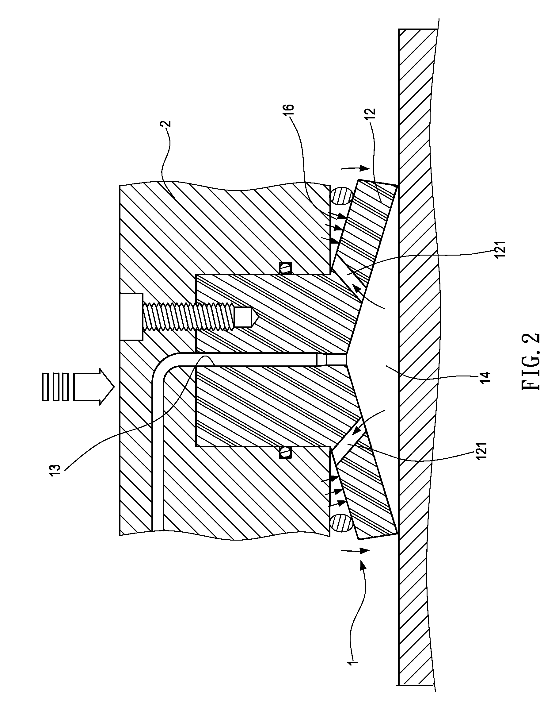
The present invention provides a self-compensating hydrostatic planar bearing device and method that can overcome the phase lag of the restrictor's reaction to bearing oil film changes by a sort of local servo-compensation of the bearing gap geometry. This device includes a flow restrictor, a first chamber, and a second chamber, which can communicate with each other through communication holes. When the load on the bearing device changes, the pressure to the first chamber will change accordingly, causing the flexible supporting unit to deform slightly and further causing the volume of the first chamber to change, thus achieving a process for self-compensating the stiffness of the bearing. The technical effect of this invention is to improve the stability and efficiency of the bearing device, reducing the likelihood of failure and improving its performance under various operating conditions.

Problems solved by technology

However, besides being costly, flow valves can be problematic in many ways.
Without the use of restrictor, the corresponding hydrostatic bearings in the hydrostatic slide system will not be able to provide any stiffness and supporting ability.
(1) As the hydrostatic slideway system is designed with specific bearing pocket configuration and flow restrictor type. Its stiffness is of fixed value and is independent to external loading. While designing the hydrostatic bearing with the other pocket configuration and restrictor type, the bearing performance characteristics must be re-calculated theoretically.
(2) In the oil supply circuit of the traditional hydrostatic bearings, the restrictors are placed upstream of the feed hole of the bearing. For one thing, those restrictors cannot be installed sufficiently close to the bearing pocket's inlet, which results in time delay of their reaction to bearing film changes. Thus, ideally, the compensation ought to find place in the bearing gap itself.
Although the aforesaid patent is feasible, it is unsatisfactory in both accuracy and reliability.
However, as oil pouch might respond quite slowly for compensating the pressure difference, the aforesaid design is not suitable for miniature slide systems.
However, pressure difference capable being compensated by the aforesaid design is limited to a very small range.
However, the oil circuit system for the aforesaid self-compensating hydrostatic bearing can be very complex and thus costly.

Method used


Image

  • Self-compensating hydrostatic planar bearing device and the method thereof
  • Self-compensating hydrostatic planar bearing device and the method thereof
  • Self-compensating hydrostatic planar bearing device and the method thereof

Examples


Embodiment Construction

[0024]For your esteemed members of reviewing committee to further understand and recognize the fulfilled functions and structural characteristics of the invention, several exemplary embodiments cooperating with detailed description are presented as the follows.

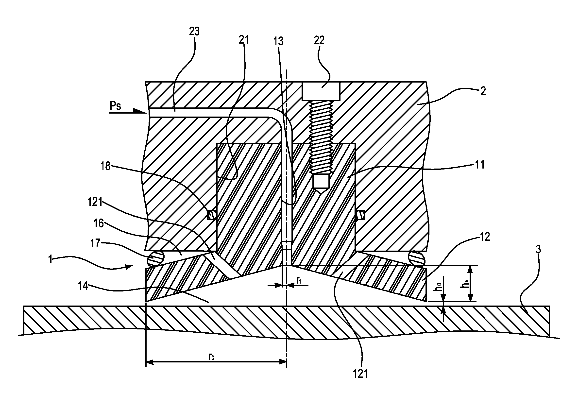
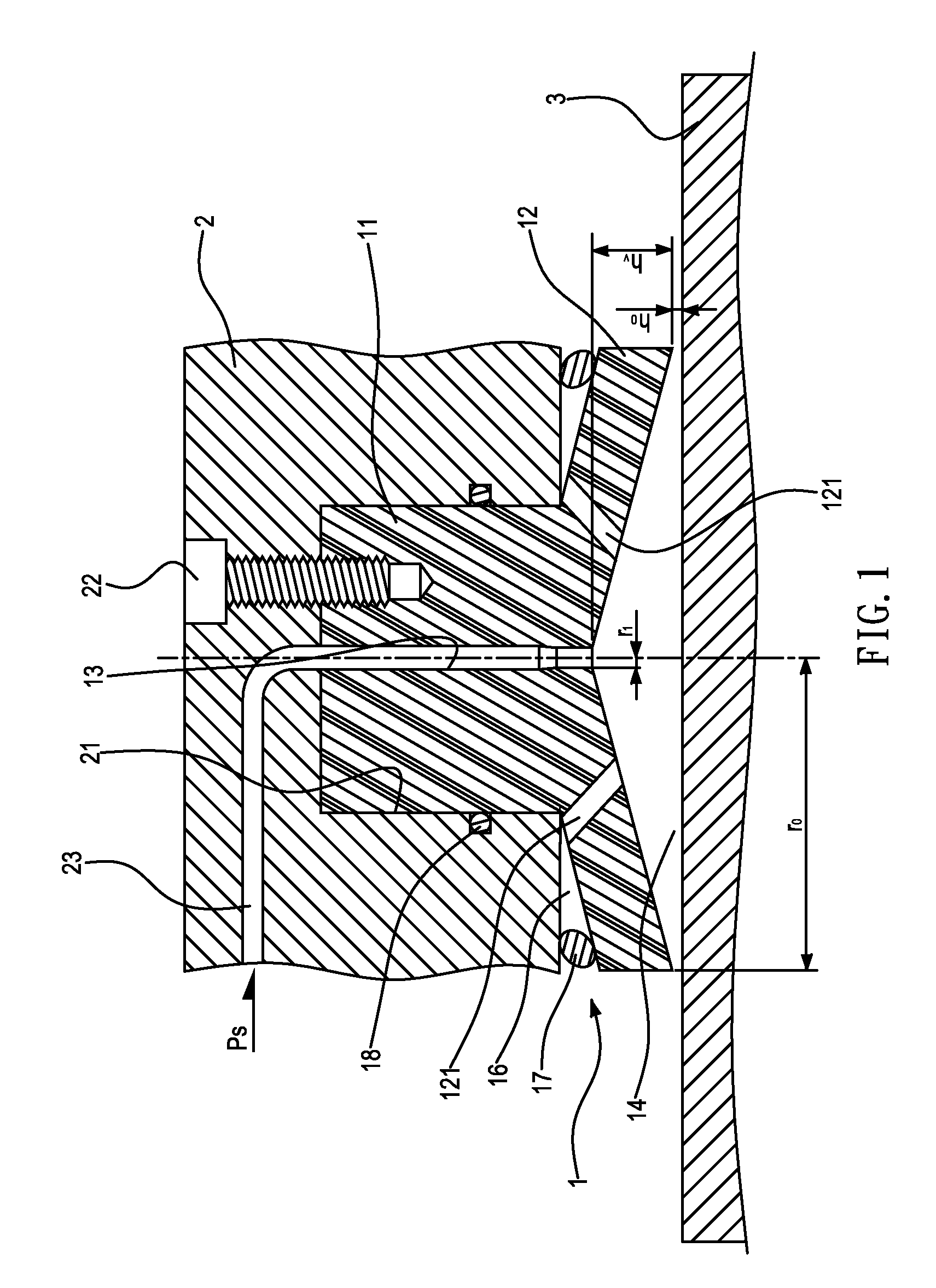
[0025]Please refer to FIG. 1, which is a sectional view of a self-compensating hydrostatic planar bearing device according to an embodiment of the invention. In of FIG. 1, the hydrostatic planar bearing device 1 is sandwiched between a slide-table 2 and a guide rail 3. In fact, depending on its size, there can be a plurality of such hydrostatic planar bearing device 1 being sandwiched between the slide-table 2 and the guide rail 3 for enabling the slide-table 2 to slide smoothly along the guide rail 3.

[0026]The hydrostatic planar bearing device 1 is configured with a flow restrictor 11, which is fitted inside a groove 21 formed on the slide-table 2 and is fixed therein by a fixing part 22, such as a screw bolt. It is noted tha...


PUM


Abstract

A self-compensating hydrostatic planar bearing device comprises: a flow restrictor, disposed on a slide-table, having a flexible supporting unit extendedly formed on an end thereof; a first chamber, formed on another end of the flow restrictor opposite to that of the flexible supporting unit for communicating with a pipe disposed penetrating through the flow restrictor; and a second chamber, formed between the supporting unit and the slide-table for communicating with the first chamber through a communication hole. Operationally, when the load is changing, the pressure to the first chamber will be changing accordingly while the pressure change will be transferred to the second chamber through the communication hole for causing the flexible supporting unit to deform and thereby further causing the volume of the first chamber to change so that the pressure of the first chamber is consequently changed therewith and thus accomplishes a self-compensating process of the bearing's stiffness.

Description

CROSS-REFERENCE TO RELATED APPLICATIONS[0001]This non-provisional application claims priority under 35 U.S.C. §119(a) on Patent Application No(s). 098115776 filed in Taiwan, R.O.C. on May 13, 2009, the entire contents of which are hereby incorporated by reference.FIELD OF THE INVENTION[0002]The present invention relates to a self-compensating hydrostatic planar bearing device and the method thereof, and more particularly, to a hydrostatic planar bearing device and method capable of overcoming the phase lag of the restrictor's reaction to bearing oil film changes by a sort of local servo-compensation of the bearing gap geometry.BACKGROUND OF THE INVENTION[0003]Hydrostatic slideway systems are commonly used as a work-table or a tool-table of metal-cutting machine tools. A hydrostatic slideway system includes a guideway unit having a pair of guide rails formed on an upper surface of a machine bed, and a slide-table unit having plural oil pockets formed respectively on a lower surface a...

Claims


Application Information

Patent Timeline
Patent Type & Authority Applications(United States)
IPC IPC(8): F16C32/06
CPCF16C29/025F16C32/067F16C32/064F16C32/0629
Inventor HUANG, HUA-CHIHYAUNG, PO-CHUN
Owner IND TECH RES INST
Learn More