Hybrid level measurement system

a level measurement and hybrid technology, applied in the direction of instruments, level indicators, measurement devices, etc., can solve the problems of critical power consumption design of the transmitter, inconvenient operation, and inability to meet the requirements of four conductors,

Active Publication Date: 2010-11-18
AMETEK MAGNETROL USA LLC
View PDF7 Cites 5 Cited by
  • Summary
  • Abstract
  • Description
  • Claims
  • Application Information

AI Technical Summary

Benefits of technology

[0015]There is disclosed in accordance with another aspect of the invention a through air level measurement instrument comprising a sensor including a transducer for transmitting a pulse signal at a target of interest and receiving reflected echoes of the pulse signal and developing an analog signal representative of the reflected echoes. An analog processing circuit is operatively coupled to the sensor for receiving the analog signal and comprises a gate for selectively transferring the analog signal to a comparator that compares the gated analog signal to a select threshold level to develop a level data signal representative of level of the target of interest. A programmed digital processing circuit is operatively coupled to the sensor and the analog processing circuit. A measurement module controls the drive circuit and evaluates the level data signal to determine material level. An echo processing module periodically evaluates a digital representation of the analog signal to determine an expected window time and expected amplitude of a reflected echo representing the target of interest and develops a gate control signal to control the gate based on expected window time and developing the select threshold level based on the expected amplitude.
[0016]There is disclosed in accordance with a further aspect of the invention a through air level measurement instrument comprising a sensor including a transducer for transmitting a pulse signal at a target of interest and receiving reflected echoes of the pulse signal and developing an analog signal representative of the reflected echoes. An analog processing circuit is operatively coupled to the sensor for receiving the analog signal and comprising a gate for selectively transferring the analog signal to a comparator responsive to a gate control signal. The comparator compares the gated analog signal to a select threshold level to develop a level data signal representative of level of the target of interest. A programmed processor is operatively coupled to the sensor and the analog processing circuit to receive the analog signal and the level data signal and to develop the gate control signal and the select threshold level signal. The processor comprises a measurement module to control the sensor and evaluate the level data signal to determine material level. An echo processing module periodically evaluates a digital representation of the analog signal to determine an expected window time and expected amplitude of a reflected echo representing the target of interest and developing the gate control signal based on expected window time and developing the select threshold level based on the expected amplitude.

Problems solved by technology

Where transmitters are remotely located, the requirement for four conductors can be undesirable due to the significant cost of cabling.
Because of these operating requirements, the design of the transmitter in terms of power consumption is critical.
As noted above, the supply energy may be very limited.
Moreover, in hazardous application environments the sensor supply energy may be very limited, to preclude the possibility of igniting flammable substances.
Signal processing methods that require substantial run time microprocessor activity to accurately perform echo location tasks conflict with the requirement that the device consume minimal amounts of electricity, or result in low measurement update rates.
Analog circuit methods for determining echo time of flight can measure efficiently and accurately but can be triggered by transient electrical noise or spurious signals resulting in erroneous measurements.

Method used


Image

  • Hybrid level measurement system
  • Hybrid level measurement system
  • Hybrid level measurement system

Examples


Embodiment Construction

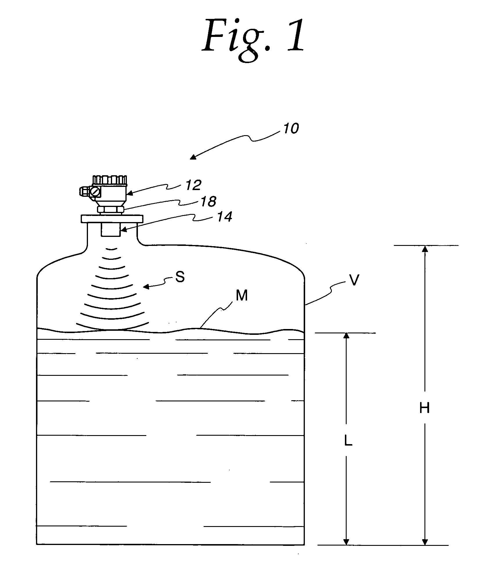
[0023]Referring to FIG. 1, a process instrument 10 according to the invention is illustrated. The process control instrument 10 uses bursts of energy for measuring a level based on time required for reflected echoes to return from the material surface of interest. Particularly, the instrument 10 uses through air ultrasound for sensing level.

[0024]While the embodiments described herein relate to an ultrasonic level sensing apparatus, various aspects of the invention may be used with other types of process control instruments for measuring various process parameters, such as a distance or range finder, as will be apparent to those skilled in the art. Moreover, the instrument may use other forms of energy where the instrument measures time required for reflected echoes to return from the material surface of interest. Distance is derived from the propagation speed of the energy burst and the elapsed time of the echo travel for the echo returning from the target of interest. This distanc...


PUM


Abstract

A measurement instrument comprises a sensor circuit comprising a drive circuit for transmitting a pulse signal at a target of interest and a receive circuit receiving reflected echoes of the pulse signal and developing an analog signal representative of the reflected echoes. An analog processing circuit is operatively coupled to the sensor circuit for receiving the analog signal and comprising a gate for selectively transferring the analog signal to a comparator that compares the gated analog signal to a select threshold level to develop a data signal representative of location of the target of interest. A programmed digital processing circuit is operatively coupled to the sensor circuit and the analog processing circuit and comprises a measurement module to control the drive circuit and evaluate the data signal to determine material location. An echo processing module periodically evaluates a digital representation of the analog signal to determine an expected window time and expected amplitude of a reflected echo representing the target of interest and developing a gate control signal to control the gate based on expected window time and developing the select threshold level based on the expected amplitude.

Description

CROSS REFERENCE TO RELATED APPLICATIONS[0001]There are no related applications.FIELD OF THE INVENTION[0002]This invention relates to a process control instrument, and more particularly, to a hybrid level measurement instrument.BACKGROUND OF THE INVENTION[0003]Process control systems require the accurate measurement of process variables. Typically, a primary element senses the value of a process variable and a transmitter develops an output having a value that varies as a function of the process variable. For example, a level transmitter includes a primary element for sensing level and a circuit for developing an electrical signal proportional to sensed level.[0004]An electrical transmitter must be connected to an electrical power source to operate. One form of such transmitter, known as a four-wire transmitter, includes two terminals for connection to a power source and two terminals for carrying the output signal proportional to the process variable. Where transmitters are remotely...

Claims


Application Information

Patent Timeline
Patent Type & Authority Applications(United States)
IPC IPC(8): G01S15/00
CPCG01F23/2962
Inventor HAYNES, KEVIN M.TURCOTTE, CHRISTOPHER P.
Owner AMETEK MAGNETROL USA LLC
Why Eureka
Try Eureka