
Vehicle control system and method using navigation data

Inactive Publication Date: 2010-11-11
DENSO CORP
View PDF14 Cites 20 Cited by
  • Summary
  • Abstract
  • Description
  • Claims
  • Application Information

AI Technical Summary

Benefits of technology

[0009]In a vehicle control system, by detecting absolute positions of the vehicle with high accuracy, traveling track information with high accuracy is stored. The vehicle is controlled according to road conditions which are determined from the stored traveling track information with high accuracy. In consequence, it is possible to achieve effective vehicle control as compared with the case of vehicle control performed according to road conditions determined based on a road map with a low accuracy.

Problems solved by technology

However, due to, for example, an error between a road on the road map indicated based on the map data and an actual road, the detected absolute position often does not conform to the road map indicated based on the map data.
In this regard, the adjustment of the optical axis direction of the headlights according to the road conditions, which are determined based on the road map, involves an inappropriate control relative to the actual road conditions in a place where the accuracy of the road map indicated based on the map data is low, such as mountain paths.

Method used


Image

  • Vehicle control system and method using navigation data
  • Vehicle control system and method using navigation data
  • Vehicle control system and method using navigation data

Examples


Embodiment Construction

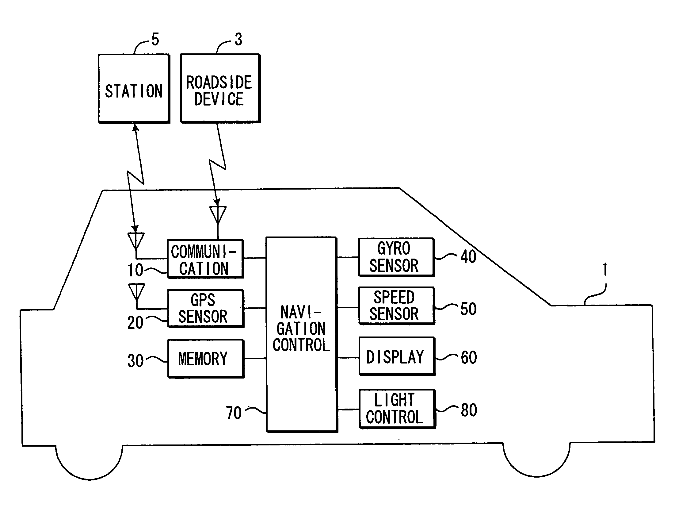
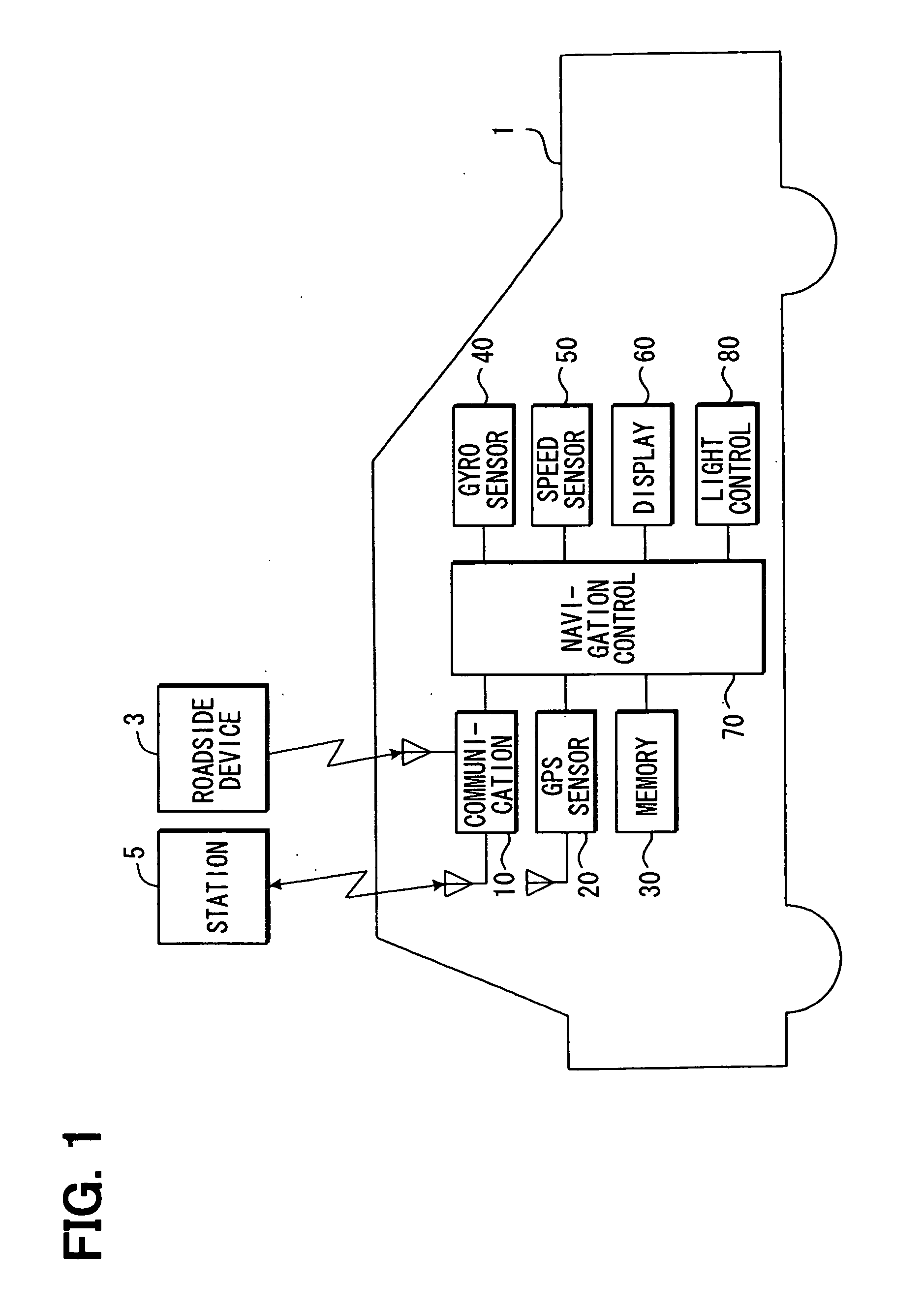
[0015]Referring first to FIG. 1, a vehicle control system is mounted on and used in a vehicle (automobile) 1. The vehicle control system is equipped with a communication unit 10, a GPS sensor 20, a memory unit 30, a gyro sensor 40, a vehicle speed sensor 50, a display 60, a navigation control unit 70, and a light control unit 80.

[0016]The communication unit 10 has two functions: a function of receiving information through a wireless personal area network from roadside devices 3 that are provided along roadsides; a function of carrying out communications through a communication network, such as the Internet, with a central station 5 (corresponding to an external server) which collects information from a plurality of vehicles on which the vehicle control system is mounted. Examples of the processing carried out by the central station 5 are a process of receiving and storing the information transmitted from a plurality of the vehicles, and a process of providing (transmitting) the stor...


PUM


Abstract

While a vehicle travels in a regular point, an absolute position of the vehicle is detected based on detection signals of a GPS sensor, a gyro sensor and a vehicle speed sensor. Then, a map matching process is performed such that the detected absolute position is corrected to be matched with a road map of map data. While the vehicle travels at a specific point, track position information of the vehicle based on the detected absolute position is stored independently of the map data. In particular, when the track position information regarding the specific point at which the vehicle is traveling at this point has been already stored, the information is sent to a light control unit, whereby the light control unit performs the optical axis control according to the traveling track indicated by the track position information.

Description

CROSS REFERENCE TO RELATED APPLICATION[0001]This application is based on and incorporates herein by reference Japanese Patent Application No. 2005-297671 filed on Oct. 12, 2005.FIELD OF THE INVENTION[0002]This invention relates to vehicle control system and method, which perform a vehicle control according to road conditions.BACKGROUND OF THE INVENTION[0003]Conventionally, a vehicle navigation system uses both absolute positioning data obtained by a satellite navigation technique using a GPS sensor and relative positioning data obtained by a dead reckoning navigation technique using a gyro sensor, a vehicle speed sensor and the like, to detect an absolute position of a vehicle. The vehicle navigation system displays the current position of the vehicle on a road map indicated based on map data. However, due to, for example, an error between a road on the road map indicated based on the map data and an actual road, the detected absolute position often does not conform to the road map ...

Claims


Application Information

Patent Timeline
IPC IPC(8): G06F19/00B60Q1/08G08G1/00G08G1/13
CPCB60Q1/085B60Q2300/322B60Q2300/324B60W40/06G08G1/096783G01C21/30G08G1/096716G08G1/096758B60W2050/0077B60W2050/0075B60W2556/45
Inventor YAMADA, KAZUNAO
Owner DENSO CORP
Learn More