
Control apparatus for hybrid vehicle

a control apparatus and hybrid technology, applied in the direction of electrical control, process and machine control, instruments, etc., can solve the problems of resonance, noise, and fluctuation of the rotational speed of the engine, and achieve the effect of suppressing vibration and nois

Inactive Publication Date: 2010-11-11
NISSAN MOTOR CO LTD
View PDF16 Cites 61 Cited by
  • Summary
  • Abstract
  • Description
  • Claims
  • Application Information

AI Technical Summary

Benefits of technology

[0008]The present invention was conceived in view of this problem. One object of the present invention is to provide a hybrid vehicle control apparatus for a hybrid vehicle having a holding element that is arranged between an internal combustion engine and an electric motor for connecting and disconnecting the internal engine and the electric motor to and from each other, in which the control apparatus suppresses an occurrence of vibrations and noise resulting from resonance when the internal combustion engine is stopped while the holding element in an engaged state.

Problems solved by technology

It has been discovered that if the engine is stopped with the holding element fully engaged, then there is the possibility that resonance will occur in a power train including the engine when the rotational speed of the engine passes through a prescribed rotational speed region as it decreases to zero.
Such resonance can cause the rotational speed of the engine to fluctuate greatly.
This situation can cause noise to occur due to a chattering (vibrating contact) of gears inside the transmission.
Such vibration and noise resulting from resonance can cause a driver to experience a feeling that something is odd about the vehicle.

Method used


Image

  • Control apparatus for hybrid vehicle
  • Control apparatus for hybrid vehicle
  • Control apparatus for hybrid vehicle

Examples


Embodiment Construction

[0016]Selected embodiments of the present invention will now be explained with reference to the drawings. It will be apparent to those skilled in the art from this disclosure that the following descriptions of the embodiments of the present invention are provided for illustration only and not for the purpose of limiting the invention as defined by the appended claims and their equivalents. Preferred embodiments of a hybrid vehicle control apparatus according to the present invention will now be explained with reference to the drawings.

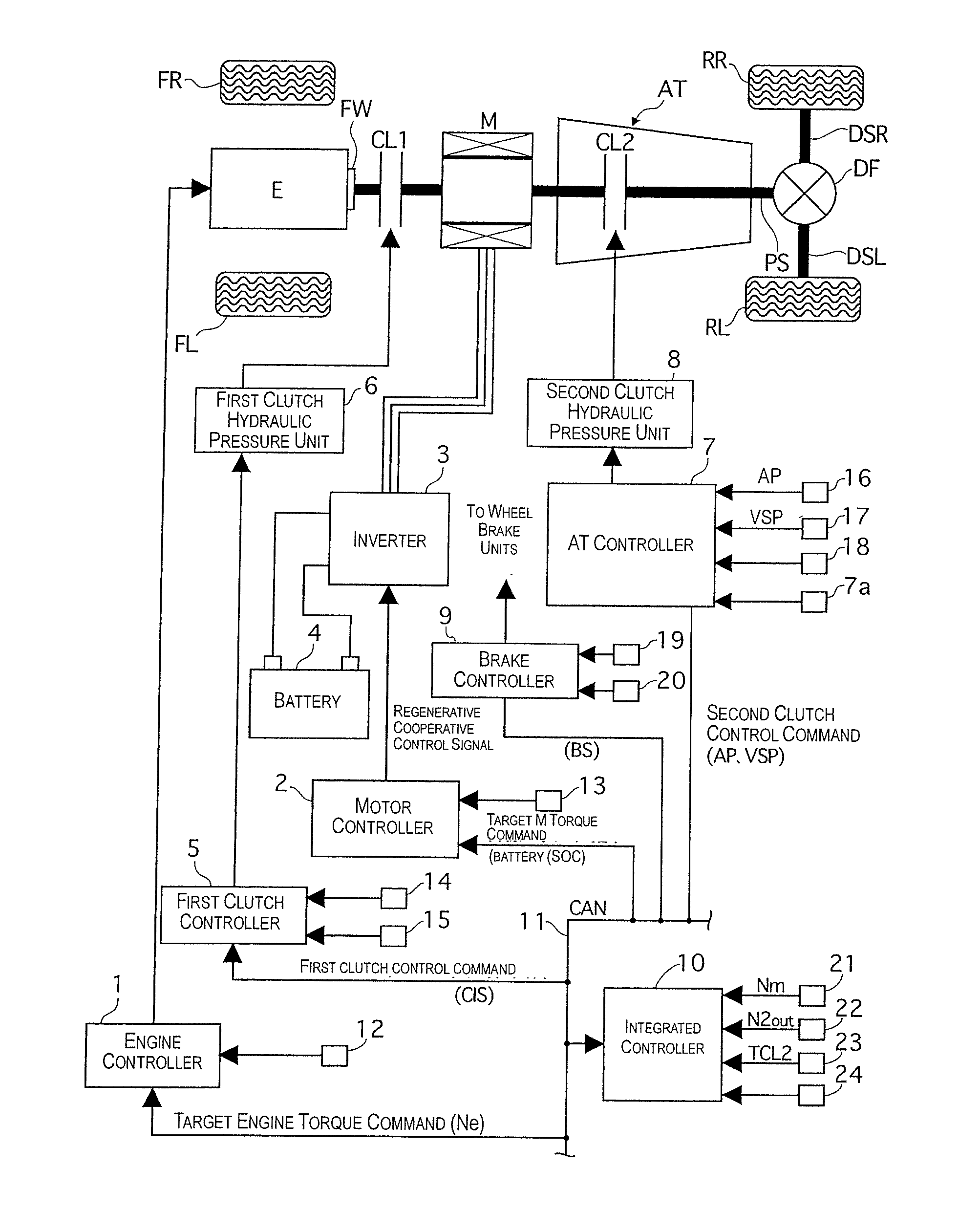
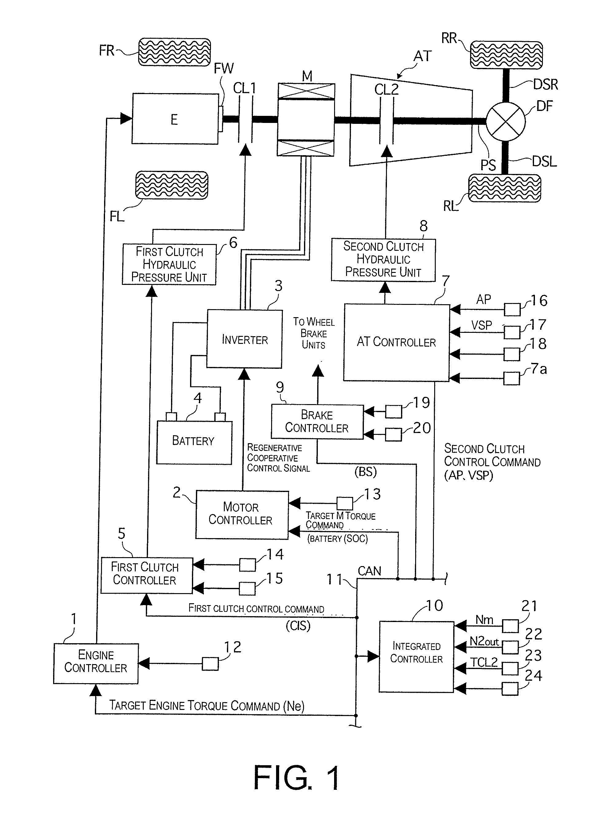
[0017]Referring initially to FIG. 1, a drive train of a hybrid vehicle having a hybrid vehicle control apparatus in accordance with an illustrated embodiment of the present invention is explained. In this example, the hybrid vehicle is arranged as a rear wheel drive hybrid vehicle. FIG. 1 is an overall schematic block diagram showing a drive train control system of the hybrid vehicle. As shown in FIG. 1, the drive train of the hybrid vehicle in the ill...


PUM


Abstract

A hybrid vehicle control apparatus is provided with an engine, an electric motor, a holding element, an automatic transmission, a range position detecting device and a controller. The holding element is arranged between the engine and the electric motor to selectively connect and disconnect the engine and the electric motor to and from each other. The automatic transmission is arranged between the electric motor and a drive wheel. The range position detecting device detects a range position of the automatic transmission selected by a driver. The controller executes a control operation serving to stop the engine while also executing a slip control serving to lower a torque transfer capacity of the holding element upon a determination that a request to stop the engine has occurred while the engine is operating, the holding element is engaged, and the automatic transmission is detected in a non-driving range.

Description

CROSS-REFERENCE TO RELATED APPLICATIONS[0001]This application claims priority to Japanese Patent Application No. 2008-055669, filed on Mar. 6, 2008. The entire disclosure of Japanese Patent Application No. 2008-055669 is hereby incorporated herein by reference.BACKGROUND OF THE INVENTION[0002]1. Field of the Invention[0003]The present invention generally relates to a hybrid vehicle control apparatus for a hybrid vehicle equipped with an engine and an electric motor as power sources. More specifically, the present invention relates to a hybrid vehicle control apparatus in which an occurrence of vibration and noise resulting from resonance can be suppressed when an engine of a hybrid vehicle is stopped while a holding element arranged between the engine and an electric motor of the hybrid vehicle is in an engaged state.[0004]2. Background Information[0005]One example of a conventional hybrid vehicle control apparatus for a hybrid vehicle is disclosed in Japanese Laid-Open Patent Publi...

Claims


Application Information

Patent Timeline
IPC IPC(8): G06F19/00B60K6/48B60K6/547B60L50/16B60W10/02B60W10/06B60W10/08B60W20/00F02D29/02F16D48/02
CPCB60K6/365Y02T10/70B60K6/48B60K6/547B60L11/14B60L2240/421B60L2240/423B60L2240/441B60L2240/445B60L2240/486B60L2240/525B60L2240/80B60W10/02B60W10/06B60W10/08B60W10/115B60W30/192B60W2510/0275B60W2510/0638B60W2510/0676B60W2510/081B60W2510/1005B60W2510/244B60W2520/10B60W2520/28B60W2540/06B60W2540/10B60W2540/12B60W2710/027B60W2710/0666B60W2710/081B60W2710/083B60W2710/1061F02D29/02Y02T10/6221Y02T10/6286Y02T10/642Y02T10/7077G06G7/70B60K6/387B60L50/16Y02T10/62Y02T10/64Y02T10/7072F02D41/042
Inventor OTOKAWA, KAYO
Owner NISSAN MOTOR CO LTD
Learn More