
Barrel-mounted device for a firearm

Inactive Publication Date: 2010-11-04
DSG TECH
View PDF3 Cites 23 Cited by
  • Summary
  • Abstract
  • Description
  • Claims
  • Application Information

AI Technical Summary

Benefits of technology

[0012]The purpose of the given invention is to increase the effectiveness of barrel-mounted devices for firearms while firing in the air and under the water.

Problems solved by technology

The need of creating barrel-mounted devices arises from the fact that the use of powerful ammunition in modern firearms while firing in the air results in the increase of recoil momentum, muzzle flash and shot blast, affecting the weapons and the shooter and thus reducing the results of firing.
These phenomena may be undesirable as they have an effect on the shooter and reduce the accuracy of aim and of fire in Aqua Shooting Ranges (see Description to patent RU 2316712 C2 Int.
However, in the course of firing in the air, gases exhausting from the compartments in the radial (lateral) direction from the line of fire increase the shot blast affecting the shooter.
The latter is not able to counteract either the increase of the vents dimensions towards the muzzle face, or a partial overlap of vents by the casing.
Fixing of this device on the barrel with a clamp cannot provide an exact fit of the barrel bore and the starting part bore and results in the fire accuracy decrease.
However, in the course of firing in the air, gases exhausting from the compartment in the radial (lateral) direction from the line of fire increase the shot blast affecting the shooter.
The latter is not able to weaken a partial redirection of the gas towards the target.
Low efficiency of this device is caused by the fact that the decrease of shot blast and muzzle flash will be proportional only to the ratio of the compartments and the barrel bore volumes.
In the course of underwater firing the compartments will be filled with water, and the gas will not be able to push water out of closed compartments.
However, gases exhausting to the compartments from the starting part do not reduce recoil momentum efficiently enough.
In the course of underwater firing the barrel and compartments are filled with water but the design of compartments and the location of vents make impossible efficient deceleration of the gases exhausting from the barrel.

Method used


Image

  • Barrel-mounted device for a firearm
  • Barrel-mounted device for a firearm
  • Barrel-mounted device for a firearm

Examples


Embodiment Construction

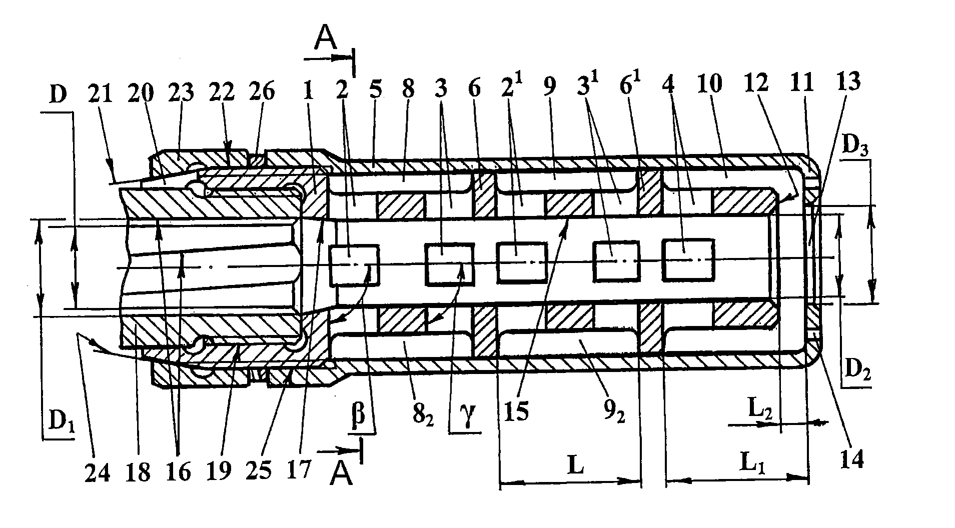
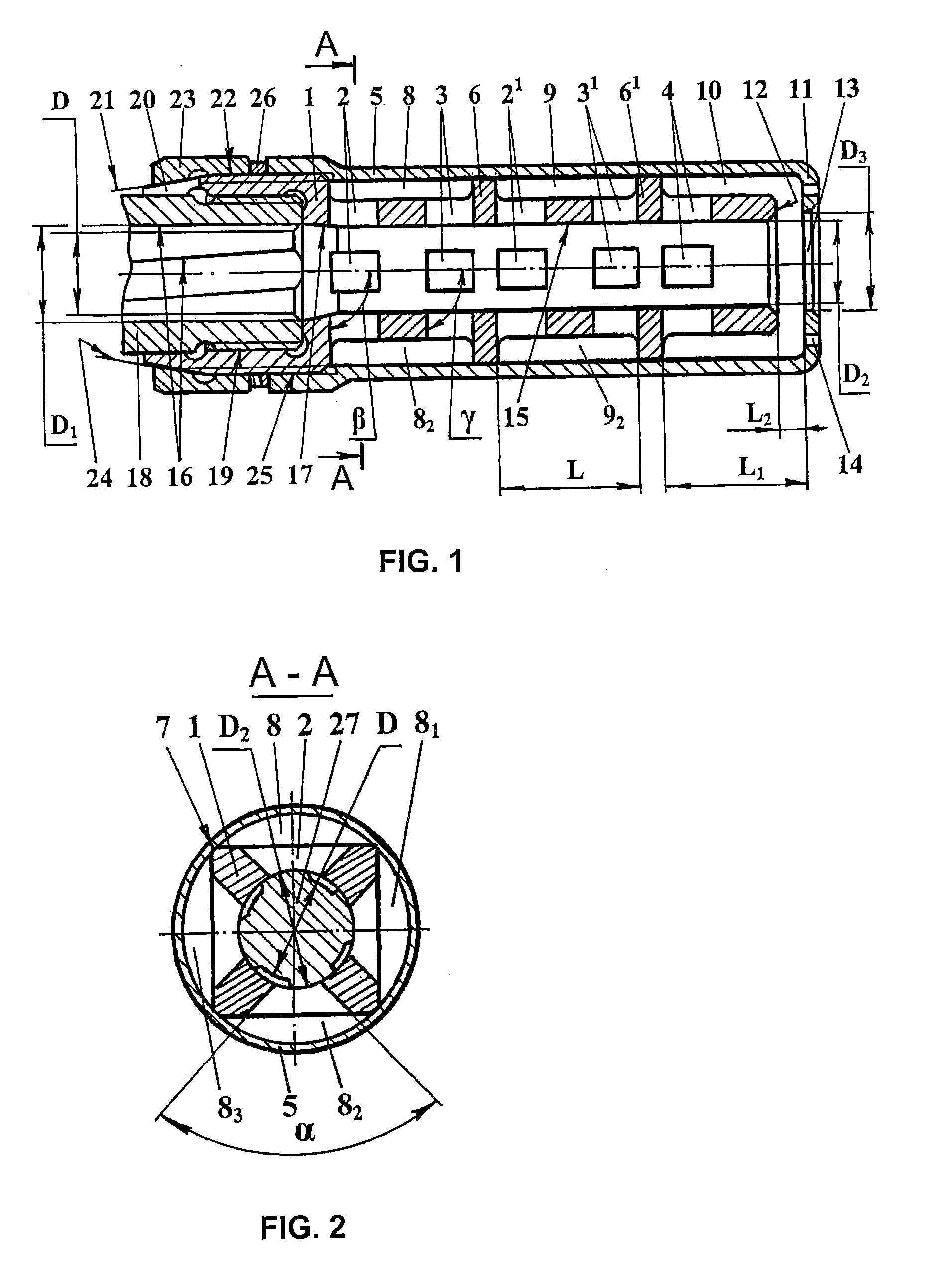
[0089]FIG. 1 and FIG. 2 show the barrel-mounted device fixed on a 7.62 mm caliber rifled barrel, where FIG. 1 shows the axial longitudinal section of the device and FIG. 2 shows the cross-section of the device in the A-A plane with a bullet moving in it.

[0090]The barrel-mounted device comprises a starting part 1 with twenty gas vents arranged in transversal rows 2, 21, 3, 31, 4 and a casing 5 separated by walls 6, 61 and longitudinal edges 7 of the starting part 1 into eight compartments 8, 81, 82, 83 and 9, 91, 92, 93, and a muzzle compartment 10. The front wall 11 of the muzzle compartment 10 projects over the muzzle face 12 of the starting part 1 and has a muzzle opening 13 and perforation 14. Compartments 8-83 and 9-93 cover gas vents rows 2, 3, 21 and 31 located on the opposite sides of compartments, and the muzzle compartment 10 covers one gas vents row and the muzzle opening 13. The smooth bore 15 of the starting part 1 is an extension of the rifled barrel bore 16 and has a s...


PUM


Abstract

The invention relates to rifled and smoothbore firearms and can be used in barrel-mounted devices for firing in the air and in the water. The inventive barrel-mounted device for firearms comprises a unit for joining to the barrel, a cap and a starting part with gas vents. The starting part bore is the continuation of the barrel bore, and there are N≧1 compartments formed between the casing and the starting part. Each compartment includes at least two gas vents and provides the possibility of gas exhaust from the starting part bore to the compartment through the first of the mentioned gas vents and gas exhaust from the compartment to the starting part bore through the second gas vent. The compartment length is 0.5-3.0 of the bore caliber and in the cross-section plane of the barrel-mounted device the minimal cross-section area of N≧1 compartments, designed for the gas flow between gas vents, ranges within 0.4-4.5 of the barrel bore area. The barrel-mounted device can comprise a muzzle compartment, which projects beyond the muzzle face of the starting part and has a front wall with a muzzle opening. The diameter of the muzzle opening equals to 1.05-1.2 of the barrel bore caliber. The said invention makes it possible to reduce recoil momentum, shot blast and muzzle flash while firing in the air, as well as to reduce recoil momentum and hydraulic impact in the course of underwater firing.

Description

TECHNICAL FIELD[0001]The invention relates to barrels of rifled and smoothbore firearms, or more specifically, to barrel-mounted devices designed for reducing recoil momentum, shot blast and muzzle flash while firing in the air, and for reducing recoil momentum and hydraulic impact in the course of underwater firing.PRIOR ART[0002]The need of creating barrel-mounted devices arises from the fact that the use of powerful ammunition in modern firearms while firing in the air results in the increase of recoil momentum, muzzle flash and shot blast, affecting the weapons and the shooter and thus reducing the results of firing. In the course of underwater firing with underwater ammunition from sporting and hunting guns and small arms (see Description to patent RU 2316718 C1 Int. C1.7 F42B 10 / 42 of 10, Feb. 2008; International Application PCT / RU2007 / 000068 of 12, Feb. 2007, publication No. WO 2007 / 126330 of 8, Nov. 2007; European Patent Application 07747813.9 of 12, Feb. 2007, publication N...

Claims


Application Information

Patent Timeline
IPC IPC(8): F41A21/32
CPCF41A21/34F41A21/28F41A21/36
Inventor POLOVNEV, ANDREY ALBERTOVICHKHASIAKHMETOV, VOLODYMYR SHAYMUKHAMETOVICH
Owner DSG TECH
Learn More