
Grain transfer control system and method

a control system and grain technology, applied in the field of agricultural equipment, can solve the problems of difficult to achieve the desired uniform, or even, fill level of the crop transport, and the underutilization of the storage capacity of the transferor-type vehicl

Active Publication Date: 2010-10-28
BLUE LEAF I P INC
View PDF11 Cites 89 Cited by
  • Summary
  • Abstract
  • Description
  • Claims
  • Application Information

AI Technical Summary

Benefits of technology

[0014]The present invention is thus directed to a grain transfer control system for automatedly controlling the transfer of grain from a mobile transferor-type vehicle, such as a combine harvester, which has opposed sides and includes a grain storage bin with a grain discharge assembly operable for effecting the transfer of grain out of said grain storage bin, to a mobile transferee-type vehicle, such as a grain cart, which has a grain holding receptacle of a predetermined length and width to generally define opposed ends and sides of the grain holding receptacle, by varying the position and speed of the transferee-type vehicle and the transferor-type vehicle relative to one another during the course of the grain transfer operation to effect a generally even fill of the transferee-type vehicle. The grain discharge assembly of the transferor-type vehicle will typically have associated therewith a discharge arm with a discharge spout for directing a flow of grain therethrough, with the discharge arm being extendible from the transferor-type vehicle to position the discharge spout at a desired position distanced from a side of transferor-type vehicle and generally along the length of the grain holding receptacle.
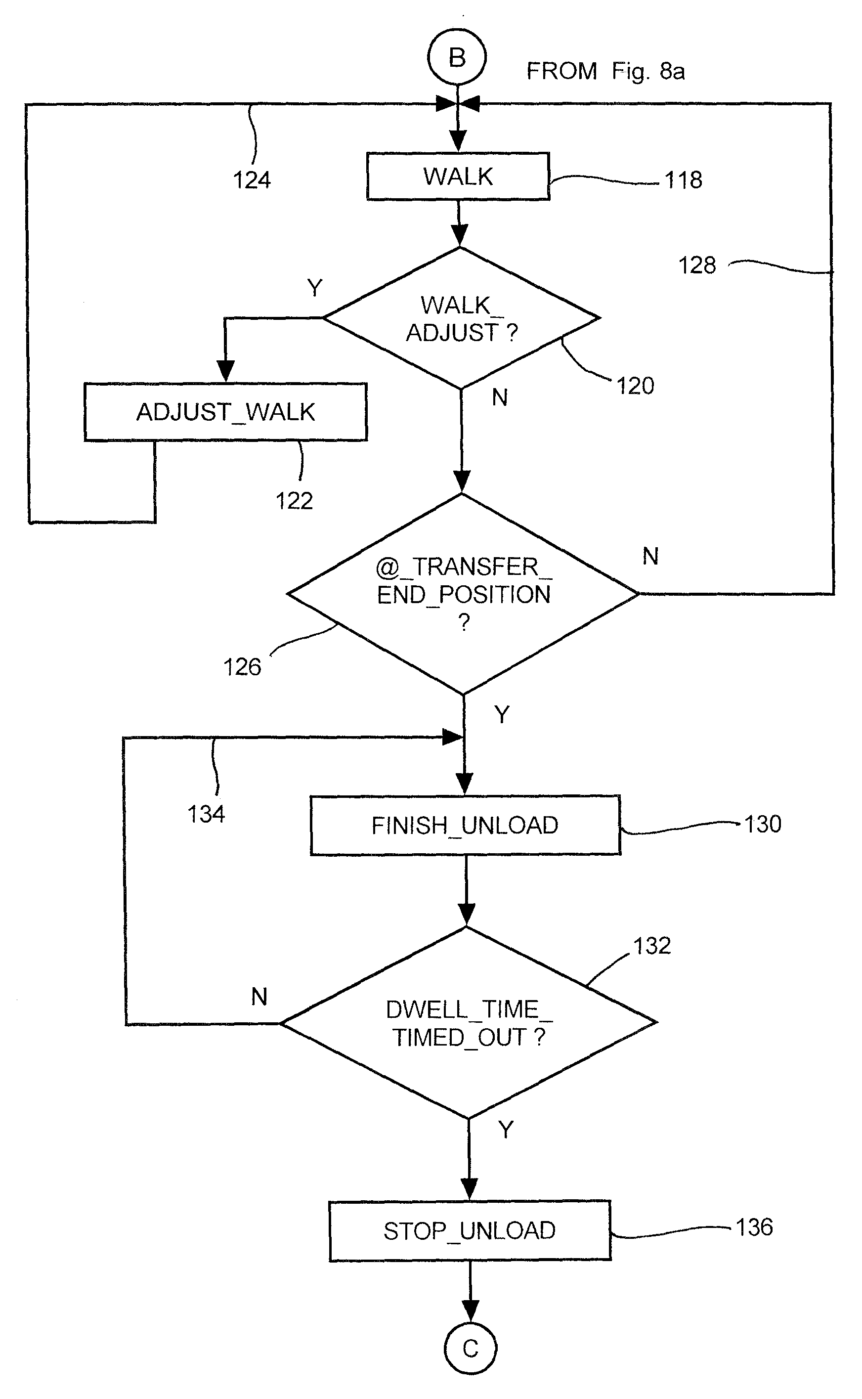
[0021]Preferably, such controller portion may take the form of a microprocessor programmed to be responsive to control information to commence a grain transfer operation when the discharge spout associated with a combine has been positioned at a transfer start position relative to the length of the grain holding receptacle of an electronically linked grain cart, to thereafter automatedly transfer grain for an initial dwell time while the discharge spout remains at said transfer start position, effect an ongoing repositioning of the grain cart relative to the combine to walk the discharge spout along at least a portion of the length of the grain holding receptacle as grain transfer continues until the discharge spout reaches a transfer end position relative to the length of the grain holding receptacle of the grain cart, continue grain transfer for a terminal dwell time while the discharge spout remains at said transfer end position, and terminate the grain transfer operation. In so controlling such grain transfer operation, such grain transfer control system effects a generally even fill of the grain holding receptacle along its length.
[0027]Consequently, the system and method of the present invention permits an electronically linked transferor-type and transferee-type vehicle to automatedly control a grain transfer operation therebetween in such a way as to effect a more even fill of a grain holding receptacle of the transferee-type vehicle along the length of such grain holding receptacle, and to be able to do so without the complexities that would be associated with systems requiring angular movements of the discharge arm and / or re-orientations of the discharge spout relative to the transferor-type vehicle, and, so also, the transferee-type vehicle, during the course of unload operations.

Problems solved by technology

Such necessity for close and continuing operator attention poses difficulties for an operator when unloading is occurring on-the-go since the operator may also be attempting to monitor and control other events at such time, including the continuing harvesting operation.
In addition, with many of such systems it has remained difficult to achieve a desired uniform, or even, fill level of the crop transport regardless of whether the transfer or grain unloading operation has been manually or automatically controlled, due in part to the sizes of the grain holding receptacles of the transport vehicles and to the nature of fill as grain is directed into the grain holding receptacle from the spout of a discharge arm associated with the transferor-type vehicle.
In general, the grain tends to pile up below the discharge spout and to assume, to some extent, the shape of a mound, with a higher grain elevation and concentration below the discharge spout and lower elevations and concentrations in radial directions therefrom, resulting in underutilization of the storage capacities of the transferor-type vehicles.
While such systems have resulted in some improvements in achieving a more uniform fill of some grain holding receptacles, they have required relatively complex subsystems for automatedly effecting the desired movements of the discharge arm and discharge spout thereof relative to the transferor-type vehicle, and, so also, the transferee-type vehicle, and for determining times for such movements as well as for ensuring that the movements will not result in crop spillage and loss during the unload operation.
The integration of such subsystems of both a transferor-type and transferee-type vehicle into a unified grain transfer control system has been challenging, especially due to the complexity of such a system.
In addition, problems with effecting an even fill have remained, especially when the crop transports have been grain carts of a larger size, with relatively large, generally rectangular (when viewed from above), grain holding receptacles, such as may be found in the Kinze 1050 and J&M 1325 carts, especially inasmuch as there are limits, while the positions of the transferor-type and transferee-type vehicle relative to one another remain fixed, as to the amount of movement and / or re-orientation that can be realized with the discharge arm and the discharge spout thereof before the discharge flow path would be directed to fall outside of the grain holding receptacle.

Method used


Image

  • Grain transfer control system and method
  • Grain transfer control system and method
  • Grain transfer control system and method

Examples


Embodiment Construction

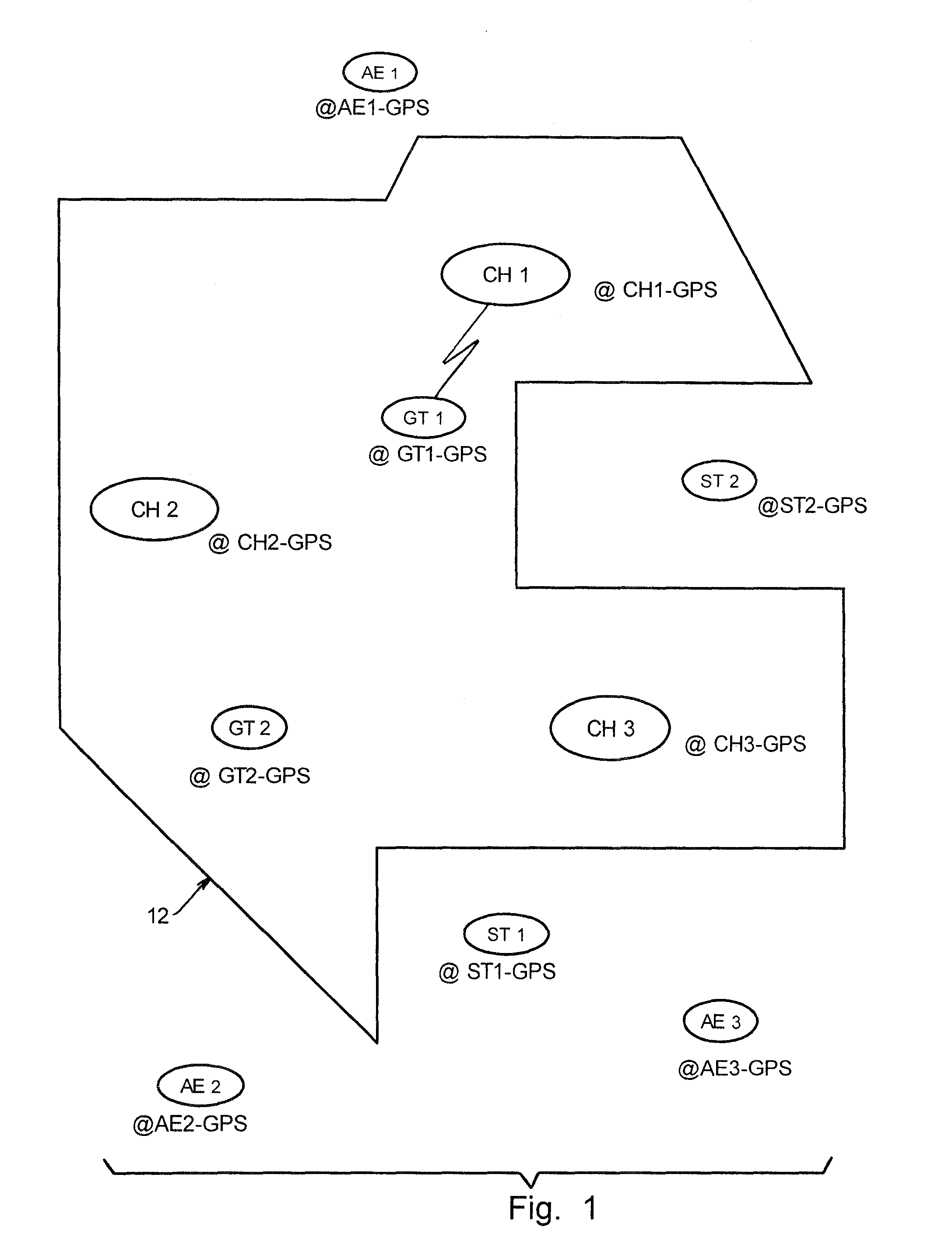
[0036]Referring now to the drawings, wherein like numbers refer to like items, FIG. 1 depicts a field 12 with a plurality of agricultural vehicles of various types therein and therearound, including combine harvesters CH1, CH2, and CH3, tractors with grain transports GT1 and GT2, and semi-trailer transporters ST1 and ST2, all of which machines are engaged in the harvesting of the particular crop in field 12, including the transport of such crop to storage. For convenience in future reference herein, the combine harvesters may often hereinafter be referred to more simply as combines or harvesters, the tractors with grain transports may often hereinafter be referred to more simply as transports or crop or grain transports or grain carts, and the semi-trailer transporters may often hereinafter be referred to more simply as transporters.

[0037]As depicted in FIG. 1, combine harvester CH1 is at location CH1-GPS, combine harvester CH2 is at location CH2-GPS, and combine harvester CH3 is at...


PUM

PropertyMeasurementUnit
lengthaaaaaaaaaa
widthaaaaaaaaaa
distanceaaaaaaaaaa

Abstract

A grain transfer control system, and method of use thereof, for automatedly controlling the transfer of grain from a mobile transferor-type vehicle, such as a combine harvester, to a mobile transferee-type vehicle, such as a crop transport, by varying the position and speed of the transferor-type and transferee-type vehicles relative to one another during the transfer operation, especially by varying the position and rate of walk of the discharge spout along at least a portion of the length of a grain holding receptacle of the transferee-type vehicle, to effect a generally even fill of the grain holding receptacle of the transferee-type vehicle along the length of the grain holding receptacle.

Description

TECHNICAL FIELD[0001]The present invention is directed to agricultural equipment, including combine harvesters and related crop transport equipment, and more particularly to a grain transfer control system, and method of use thereof, for automatedly controlling the transfer of grain from a mobile transferor-type vehicle, such as a combine harvester, to a mobile transferee-type vehicle, such as a crop transport, by varying the position and speed of the transferor-type and transferee-type vehicles relative to one another during the transfer operation, especially by varying the position and rate of walk of the discharge spout along at least a portion of the length of a grain holding receptacle of the transferee-type vehicle, to effect a generally even fill of the grain holding receptacle of the transferee-type vehicle.BACKGROUND ART[0002]For many years, agricultural equipment, sometimes denoted herein by the abbreviation AE, and the individual agricultural machines of such agricultural...

Claims


Application Information

Patent Timeline
Patent Type & Authority Applications(United States)
IPC IPC(8): G06F19/00
CPCA01B69/008
Inventor RINGWALD, JUSTIN R.FOSTER, CHRISTOPHER A.
Owner BLUE LEAF I P INC
Learn More