
Interferometric seismic data processing

Active Publication Date: 2010-10-21
WESTERNGECO LLC
View PDF4 Cites 67 Cited by
  • Summary
  • Abstract
  • Description
  • Claims
  • Application Information

AI Technical Summary

Benefits of technology

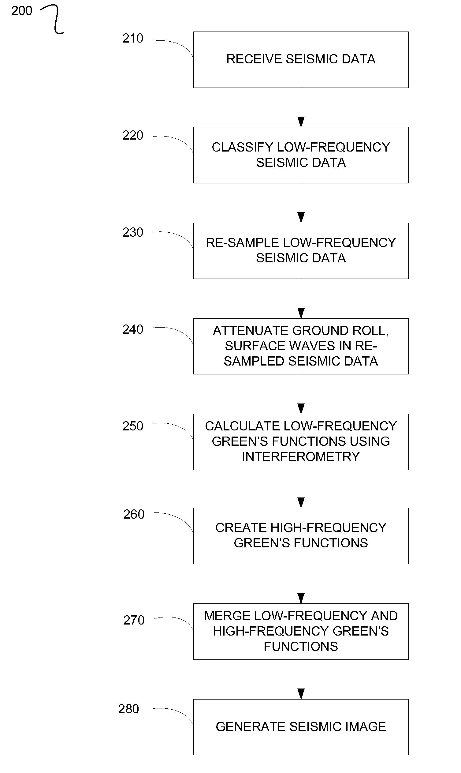
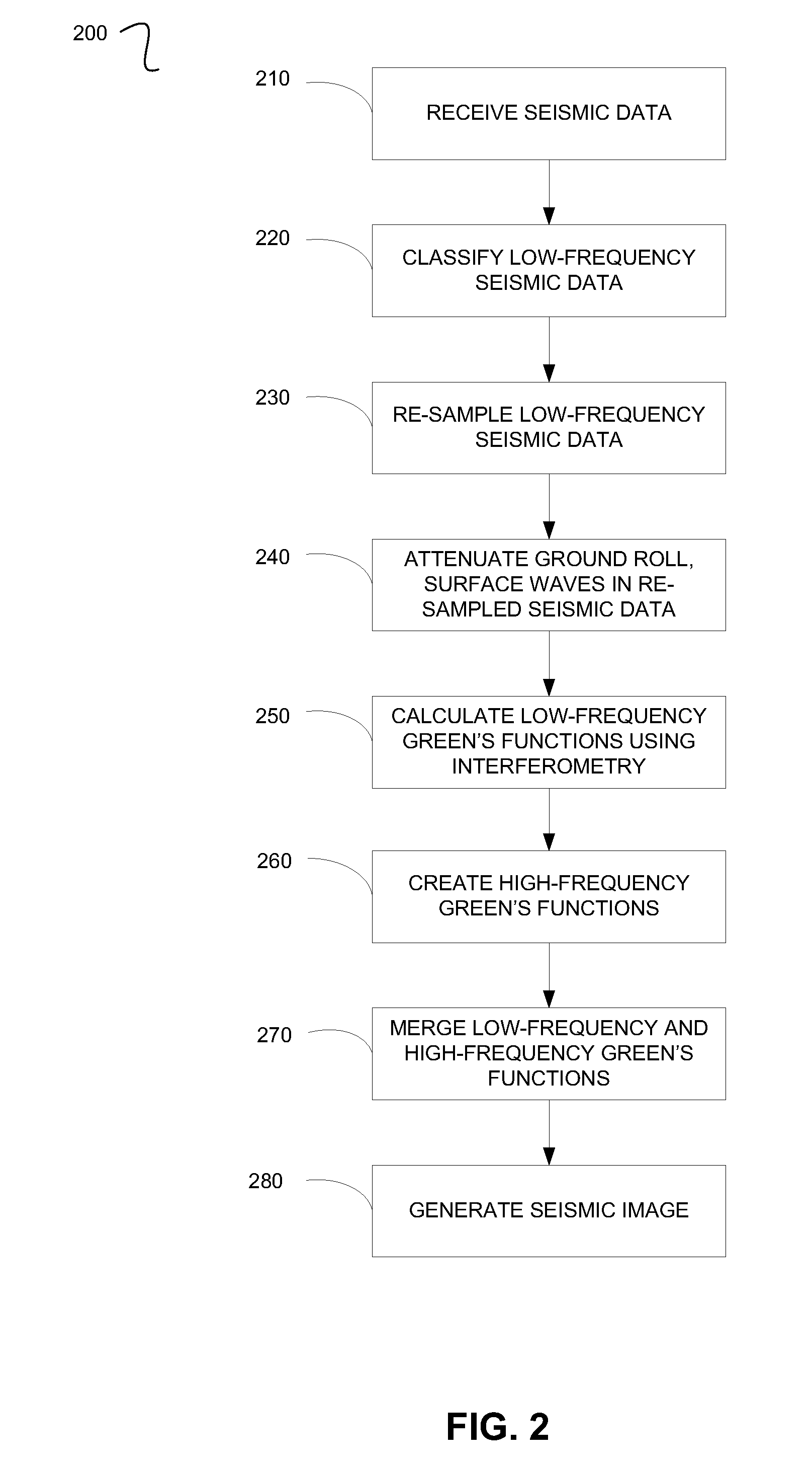
[0008]Described herein are implementations of various technologies for a method for processing seismic data. In one implementation, the method includes receiving the seismic data from two sensors in a seismic survey, classifying the seismic data below and equal to a predetermined frequency as low-frequency seismic data, calculating a set of low-frequency Green's functions using interferometry on the low-frequency seismic data, processing high-frequency seismic data of the seismic data to create a set of high-frequency Green's functions at one or more source locations of the seismic survey, merging the set of low-frequency Green's functions and the set of high-frequency Green's functions to create a set of broad-band Green's functions at the source locations, and generating a seismic image using the set of broad-band Green's functions.
[0009]In another implementation, the method includes receiving the seismic data from two sensors in a seismic survey, classifying the seismic data above and equal to a predetermined frequency as high-frequency seismic data and below and equal to the predetermined frequency as low-frequency seismic data, re-sampling the low-frequency seismic data based on the predetermined frequency, calculating a set of low-frequency Green's functions using interferometry on the re-sampled low-frequency seismic data, processing the high-frequency seismic data to form a set of high-frequency Green's functions at one or more source locations of the seismic survey, merging the set of low-frequency Green's functions with the set of high-frequency Green's functions to generate a set of broad-ba

Problems solved by technology

However, there may be situations where a non-regular distribution of the sensors is preferred or where the source and the sensors may be positioned at different depth levels.
However, acquiring low-frequency seismic data may be difficult.
However, the low-frequency output from vibroseis sources is limited by the size of the vibroseis, and its sweep time.

Method used


Image

  • Interferometric seismic data processing
  • Interferometric seismic data processing
  • Interferometric seismic data processing

Examples


Embodiment Construction

[0017]The discussion below is directed to certain specific implementations. It is to be understood that the discussion below is only for the purpose of enabling a person with ordinary skill in the art to make and use any subject matter defined now or later by the patent “claims” found in any issued patent herein.

[0018]The following paragraph provides a brief summary of various techniques described herein. In general, various techniques described herein are directed to a system for processing seismic data. Seismic data may be collected using active and passive surveying of a subsurface region. The passive surveying may record seismic activity continuously and particularly including periods between source firings in the active survey. Generally, the passive surveying enables recording of low-frequency seismic response, while the active surveying may record high-frequency seismic data. However, there is some overlap in the frequencies.

[0019]The seismic data may be split between the hig...


PUM


Abstract

Implementations of various technologies for a method for generating a seismic image of a subsurface are described herein. Seismic data may be received from two sensors in a seismic survey. The seismic data below and equal to a predetermined frequency may be classified as low-frequency seismic data. The low-frequency seismic data may be re-sampled based on the predetermined frequency. A set of low-frequency Green's functions may be calculated using interferometry on the re-sampled low-frequency seismic data. High-frequency seismic data of the seismic data may be processed to create a set of high-frequency Green's functions at one or more source locations of the seismic survey. The set of high-frequency Green's functions may be merged with the set of low-frequency Green's functions to create a set of broad-band Green's functions. The seismic image may be generated using the set of broad-band Green's functions at the source locations.

Description

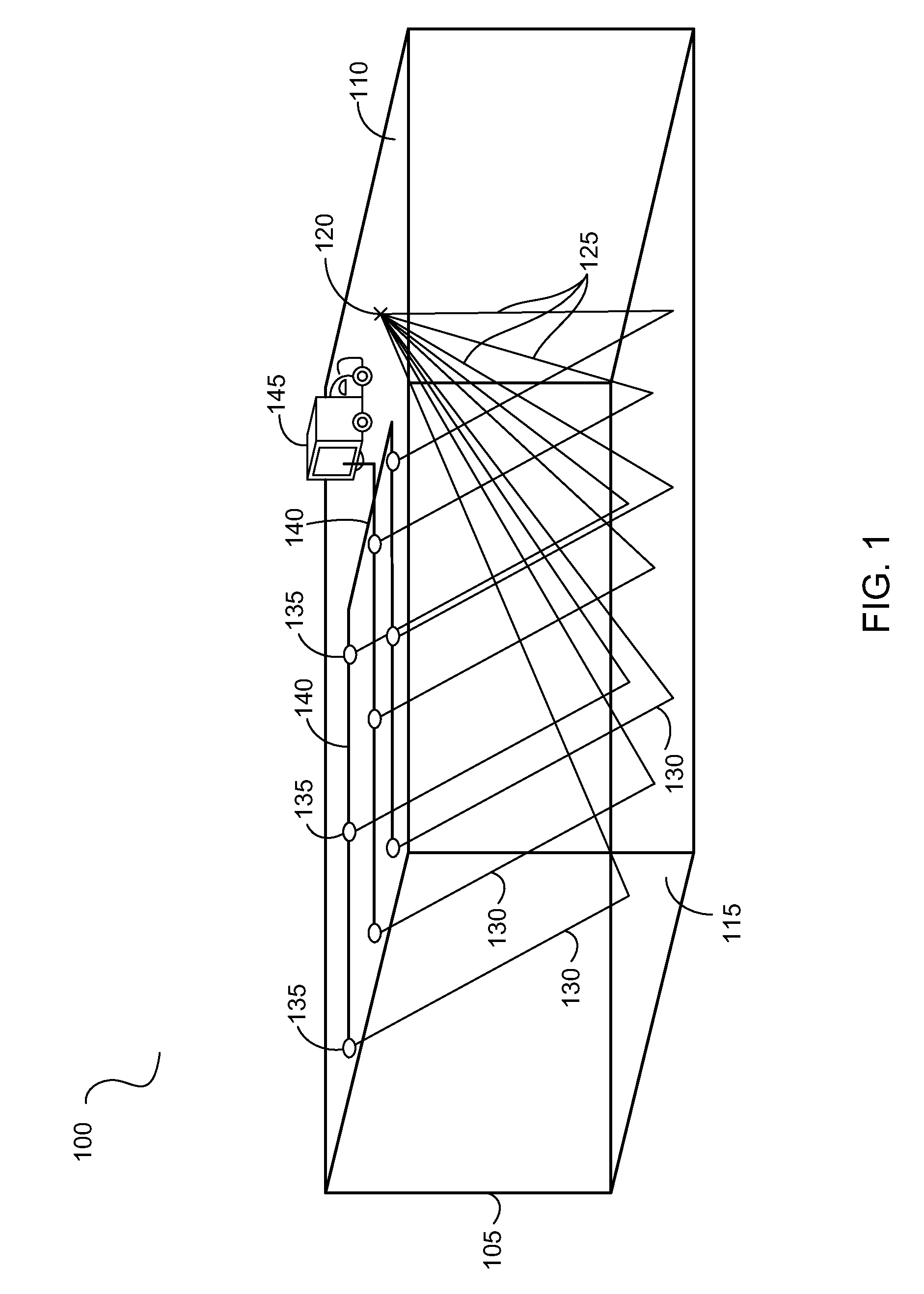
BACKGROUND[0001]1. Field of the Invention[0002]Implementations of various technologies described herein generally relate to methods and systems for processing seismic data.[0003]2. Description of the Related Art[0004]The following descriptions and examples are not admitted to be prior art by virtue of their inclusion within this section.[0005]Seismic data signals are typically acquired by measuring and recording data during a seismic survey. A seismic survey may be performed by repeatedly firing an impulsive seismic energy source at the surface of the earth, sea or seafloor and recording the received signals at a set of sensors. The sensors may typically be situated at the same surface as the source, but laterally displaced on regular grid positions. However, there may be situations where a non-regular distribution of the sensors is preferred or where the source and the sensors may be positioned at different depth levels. In a typical seismic survey, the source and the sensors may b...

Claims


Application Information

Patent Timeline
IPC IPC(8): G01V1/28G01V1/34
CPCG01V2210/675G01V1/366
Inventor ROBERTSSON, JOHAN O. A.RICKETT, JAMES
Owner WESTERNGECO LLC
Learn More