
Atmospheric water collection device

a technology of atmospheric water and collection device, which is applied in the field of atmospheric water collection, can solve the problems of increasing global concerns about insufficient potable water sources, increasing the number of deaths, and increasing the number of deaths, and deteriorating the problem of capacity and purity

Active Publication Date: 2010-10-21
MADGE DON MR
View PDF8 Cites 14 Cited by
  • Summary
  • Abstract
  • Description
  • Claims
  • Application Information

AI Technical Summary

Benefits of technology

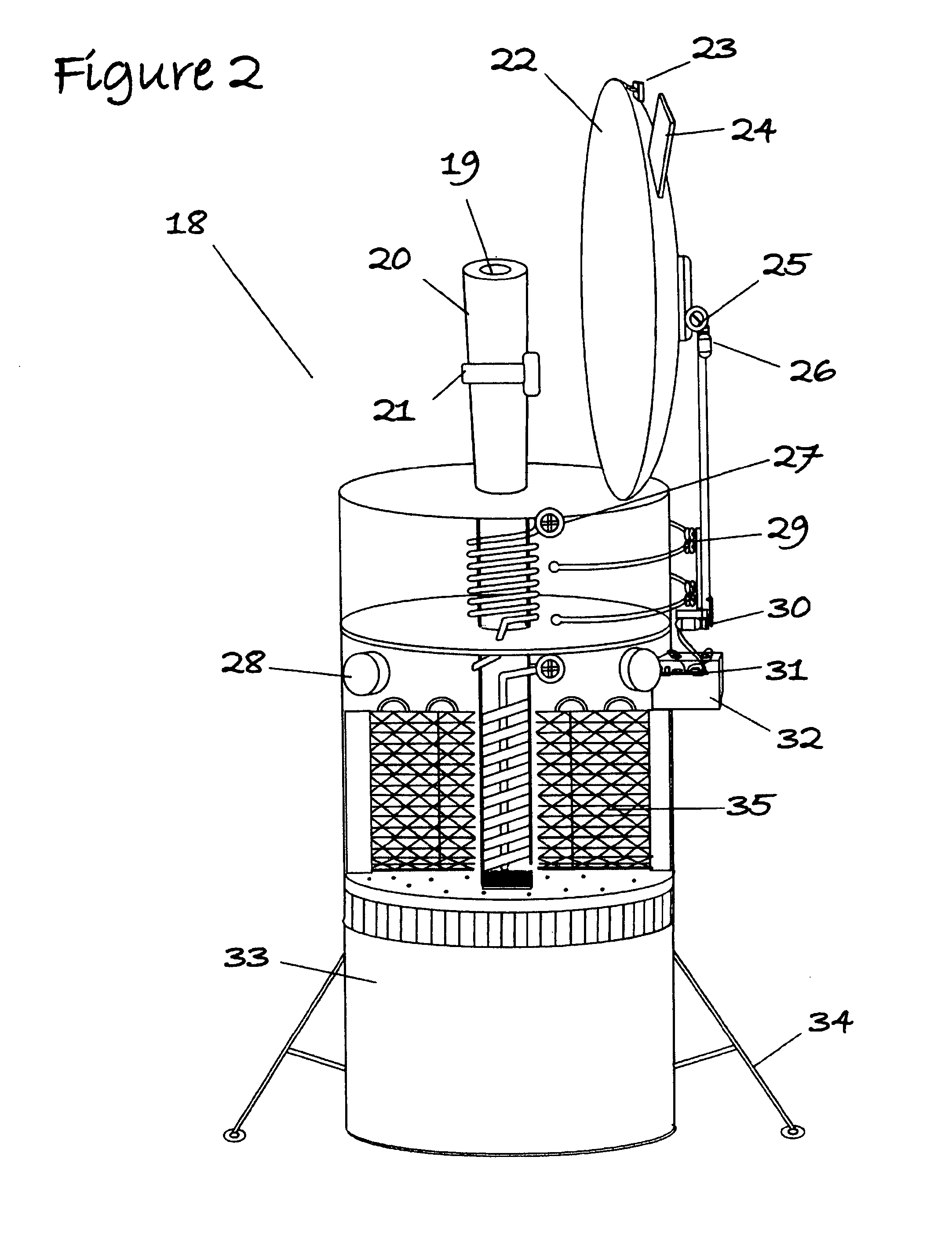
"The present invention is a device that extracts moisture vapor from atmospheric air for use as a fresh water source. The device is simple, practical, and economical, and can be used in most regions of the world. It can be powered by the sun or other natural resources, and its function is enhanced by the use of materials that increase the surface area upon which condensation occurs. The device can also be powered by a battery or other conventional power sources to improve its capability. The device includes a parabolic-shaped backdrop reflector that focuses solar energy on a generator pipe and a convection tube, and a means to draw air into the device and collect the water it produces. The invention offers flexibility and can be easily modified for different uses. It is a more efficient and cost-effective alternative to conventional refrigeration technology."

Problems solved by technology

In recent years, global concerns regarding insufficient potable water sources have grown to epidemic proportions.
Unfortunately, these water sources are not sustainable and continue to decline both in capacity and purity at alarming rates.
As each year passes, the problem worsens due to factors such as climate changes, environmental pollution, and population growth.
In a growing number of regions in the world there is inadequate water for industry, agriculture and / or drinking.
Unfortunately, many of these processes produce considerable pollutants and are costly and impractical for application where power is not readily available.
In addition, there is the need for water transport systems to transport the water to inland locations, which poses a lack of economic feasibility.
Unfortunately, this major renewable source of water is hardly being utilized.
These technologies are not suitable for much of the world's population where artificial power sources are not readily available.
Unfortunately, this process can only be used in select areas where the presence of fog is frequent and predictable.

Method used


Image

  • Atmospheric water collection device
  • Atmospheric water collection device
  • Atmospheric water collection device

Examples


Embodiment Construction

[0036]Generally, the present invention provides a method and system for collecting water from atmospheric air.

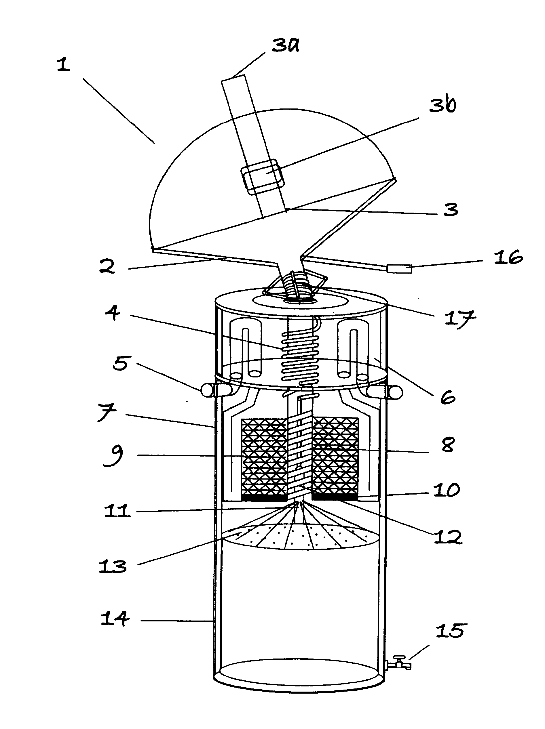
[0037]Turning to FIG. 1, a side view of a first embodiment of a water collection device is shown and indicated as 1.

[0038]This embodiment is a solar powered heat exchange system that supplies a controlled temperature to allow efficient function of the cooling system. This embodiment has many potential modifications and the required heat source may be generated by a wide variety of gases or electrically such as with 120 VAC or 12 VDC voltage.

[0039]With the preferred condenser design, refrigeration happens in intermittent cycles to coincide with available solar energy using calcium chloride as the absorber and pure ammonia as the refrigerant with the distinct advantage that salt does not evaporate during the heating process. Plumbing of the device may be divided into six parts: a generator 3 for heating the salt-ammonia mixture; a condenser coil 4 for cooling in the condenser ...


PUM

PropertyMeasurementUnit
areaaaaaaaaaaa
chemicalaaaaaaaaaa
condensing areaaaaaaaaaaa

Abstract

The present invention is directed at a solar powered heat exchange system preferably used to drive a water collection device, which condenses water vapour in atmospheric air to water. The device comprises means for drawing the atmospheric air into the device; means for condensing the moisture vapour in the atmospheric air into water; and means for collecting the water.

Description

CROSS REFERENCE TO RELATED APPLICATIONS[0001]This application is a continuation of application Ser. No. 10 / 963,646 filed Oct. 14, 2004 and which claims the benefit of U.S. Provisional Application No. 60 / 510,155, filed Oct. 14, 2003, which is incorporated herein by reference.FIELD OF THE INVENTION[0002]The present invention relates in general with water collection and more specifically to an atmospheric water collection device.BACKGROUND OF THE INVENTION[0003]In recent years, global concerns regarding insufficient potable water sources have grown to epidemic proportions. The most viable sources of fresh water include water provided by lakes, rivers, and artesian wells. Unfortunately, these water sources are not sustainable and continue to decline both in capacity and purity at alarming rates. As each year passes, the problem worsens due to factors such as climate changes, environmental pollution, and population growth. In a growing number of regions in the world there is inadequate w...

Claims


Application Information

Patent Timeline
Patent Type & Authority Applications(United States)
IPC IPC(8): F25D21/14B01D5/00F24S20/20
CPCB01D5/0006B01D5/0039Y02E10/41B01D5/0081F24J2/07B01D5/0072F24S20/20Y02E10/40
Inventor RITCHEY, JONATHAN G.
Owner MADGE DON MR
Learn More