Running pattern calculating apparatus and running pattern calculating method

Active Publication Date: 2010-10-14
TOYOTA JIDOSHA KK
View PDF1 Cites 23 Cited by
  • Summary
  • Abstract
  • Description
  • Claims
  • Application Information

AI Technical Summary

Benefits of technology

[0014]This invention thus provides a running pattern calculating apparatus and a running pattern calculating method able to improve total optimization regarding fuel efficiency or the like by avoiding a local minimum problem due to a discontinuity in engine characteristics, without fixing an operating pattern.
[0015]Also, the invention is able to more efficiently coordinate driver operations with vehicle control based on a travel plan. As a result, the travel plan is able to be achieved to an even greater level.
[0026]According to the first and second aspects, the local minimum problem due to the discontinuity of the engine characteristics can be avoided without fixing the operating pattern, so total optimization with respect to fuel efficiency or the like can be improved.
[0028]This assist control apparatus executes control that defines a plurality of sections corresponding to the running state with respect to the target speed / acceleration pattern, and assists in achieving the travel plan for each defined section. Accordingly, operations by the driver and vehicle control based on a travel plan can be more effectively coordinated. As a result, the travel plan is able to be achieved to an even greater level.
[0030]Accordingly, compatibility between vehicle control based on the travel plan and operations by the driver can be improved. As a result, the travel plan is able to be achieved to an even greater level. In other words, the assist control apparatus performs active assist control, and actively provides information related to the running state or information related to the difference to the driver. Accordingly, compatibility between vehicle control and operations by the driver can be improved by the mutual interaction of these. As a result, the travel plan can be realized with even greater performance. Also, the assist control apparatus outputs information related to the running state and / or information related to the difference between the target pattern and the driver input, so even if the vehicle is actively assist-controlled, feelings of unpleasantness or abruptness that the driver may have with respect to the assist control can be effectively suppressed.

Problems solved by technology

However, when attempting to apply the optimization method to fuel efficiency evaluation, the engine has a discontinuous characteristic in which the efficiency is worst at low engine speeds (such as approximately 800 rpm (idle speed) to 1500 rpm) and good at an engine speed of zero as well as at medium and high engine speeds.
Therefore, even if the evaluation function process is repeated in an attempt at total optimization, a running pattern having a running state that stops the engine (i.e., zero rpm) is unable to be obtained, and as a result, an operating pattern obtained by the optimization method performed to improve fuel efficiency does not necessarily end up to be a fuel efficient operating pattern.
That is, when the related optimization method is applied as it is, the engine efficiency conversely decreases in a region (near a low engine speed) where the engine speed decreases toward zero (at which the engine is stopped) from an engine speed where the engine efficiency is good (i.e., a medium or high engine speed), so the fuel efficiency becomes worse and an operating pattern that includes low vehicle speeds ends up being rejected.
However, in the related optimization method, although localized optimization is performed with respect to fuel efficiency or the like, total optimization will not necessarily be achieved.
However, a repetitive pattern that is based on a calculation that will further improve the overall fuel efficiency from departure to arrival while the vehicle is actually traveling is not generated.
However, the method described in JP-A-2006-327545 simply appropriates the results of a fixed pattern and does not include adjustments of the specific acceleration and the like in parts.
Also, with the methods described in JP-A-2007-187090 and JP-A-2007-291919, although localized improvements in fuel efficiency are realized using the maps related to speed and vehicle-to-vehicle distance, these publications do not consider total optimization.

Method used


Image

  • Running pattern calculating apparatus and running pattern calculating method
  • Running pattern calculating apparatus and running pattern calculating method
  • Running pattern calculating apparatus and running pattern calculating method

Examples


third example embodiment

[0122][Third Example Embodiment] Next, the invention will be described with reference to the drawings. Incidentally, an example in which there is an emphasis on fuel efficiency in the travel plan will be described, but the invention is not limited to this example embodiment.

[0123]First, the outline of the third example embodiment will be described. Known representative examples of a fuel efficiency assist system include “ECO mode” by Toyota Motor Corporation, “ECON” by Honda Motor Co., Ltd., and “SI-DRIVE” by Fuji Heavy Industries Ltd. The systems of these companies are also referred to as light accelerator assist control or ECO mode control, and change the accelerator input by the driver into input that will moderately improve fuel efficiency. Also, these systems enable the driver to select the mode with a switch or the like.

[0124]However, with these systems, the operational input by the driver is the agent (the solution), and moreover, the control unit is unable to determine wheth...


PUM


Abstract

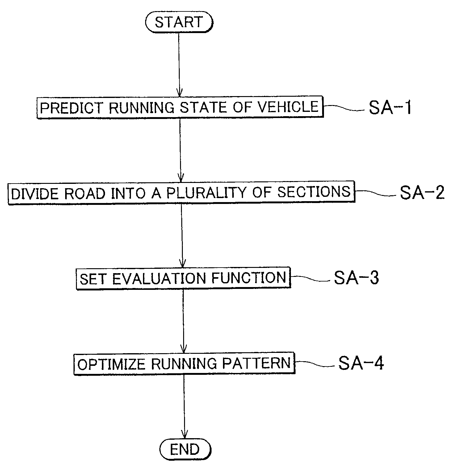
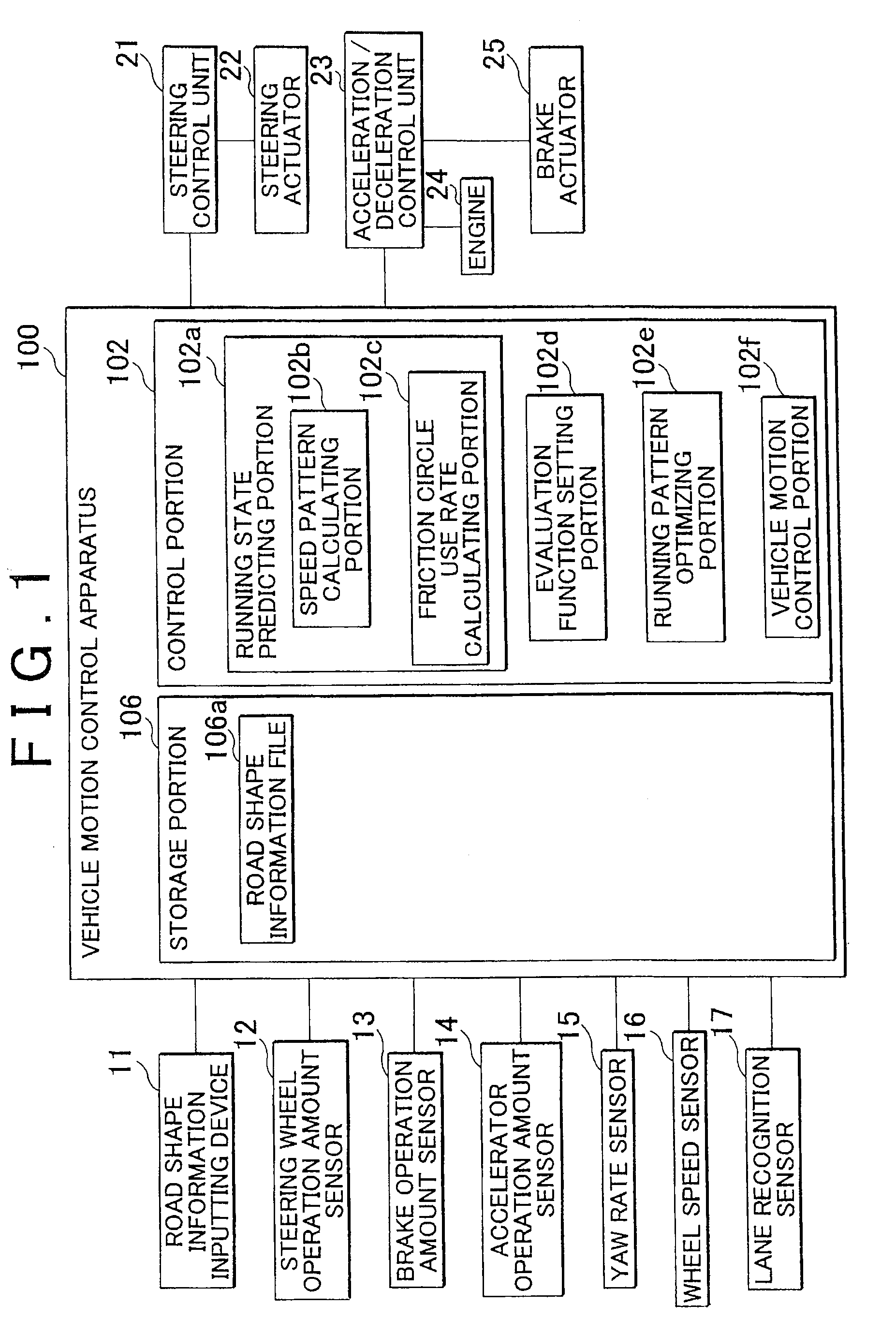
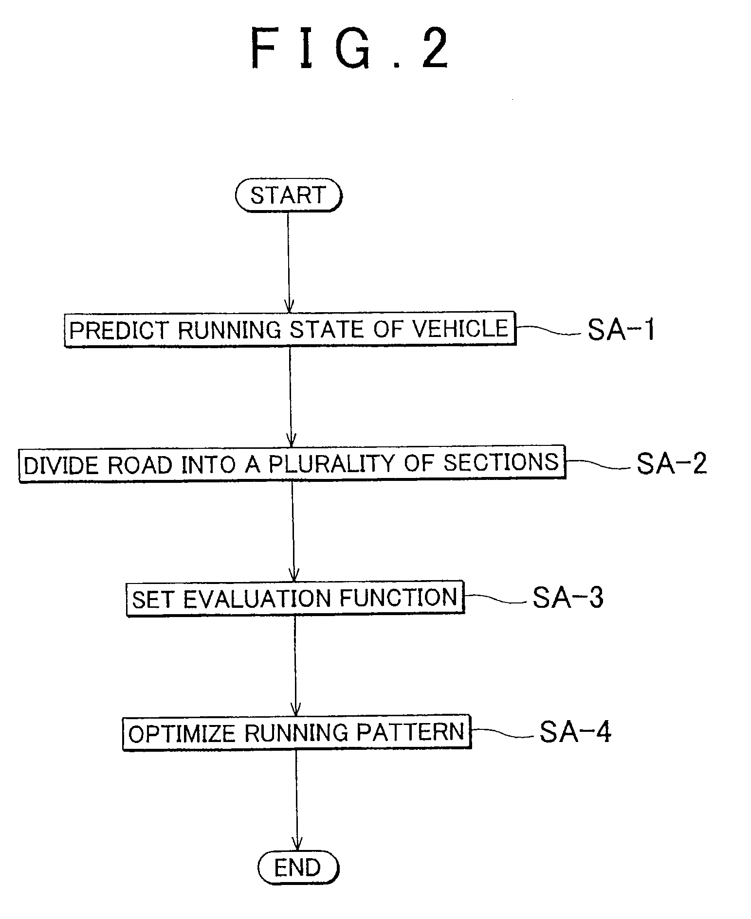
A running pattern calculating apparatus and running pattern calculating method that stores road information; predicts a running state when the vehicle will travel on a road, based on the stored road information; divides the road into a plurality of sections based on the predicted running state and sets an evaluation function for each road section; and calculates a running pattern of the vehicle that will travel on the road, based on the evaluation function set for each road section.

Description

INCORPORATION BY REFERENCE[0001]The disclosure of Japanese Patent Applications No. 2009-097313 filed on Apr. 13, 2009 and No. 2010-039340 filed on Feb. 24, 2010 including the specifications, drawings and abstracts is incorporated herein by reference in its entirety.BACKGROUND OF THE INVENTION[0002]1. Field of the Invention[0003]The invention relates to a running pattern calculating apparatus and a running pattern calculating method.[0004]2. Description of the Related Art[0005]The increase in the price of crude oil last year and the need for technology to improve the environment by reducing CO2 and the like have made improving fuel efficiency a top priority. In the past, coasting has been empirically known as an ideal way to improve fuel efficiency in eco-run competitions to see how many kilometers a vehicle can travel on a circuit or the like on only one liter of gasoline, for example. Also, in a vehicle in which the engine can be stopped while the vehicle is traveling, such as with...

Claims


Application Information

Patent Timeline
IPC IPC(8): G06G7/70
CPCB60W50/085B60W50/0098
Inventor TAGUCHI, KOJIMATSUNAGA, MASAKI
Owner TOYOTA JIDOSHA KK
Why Eureka
Try Eureka