Analyzing apparatus
a technology of analyzing apparatus and analyzing device, which is applied in the direction of liquid/fluent solid measurement, machine/engine, dynamo-electric motor control, etc., can solve the problems of low efficiency, achieve stable engagement, reduce the swinging frequency of the analyzing device, and reduce the impact
- Summary
- Abstract
- Description
- Claims
- Application Information
AI Technical Summary
Benefits of technology
Problems solved by technology
Method used
Image
Examples
first embodiment
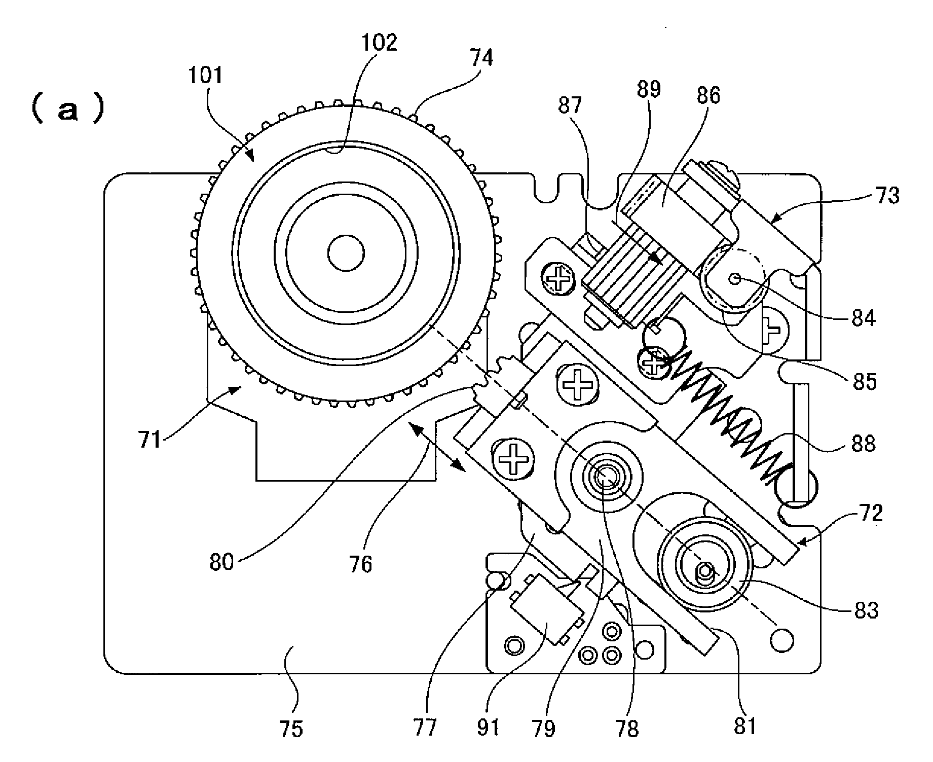
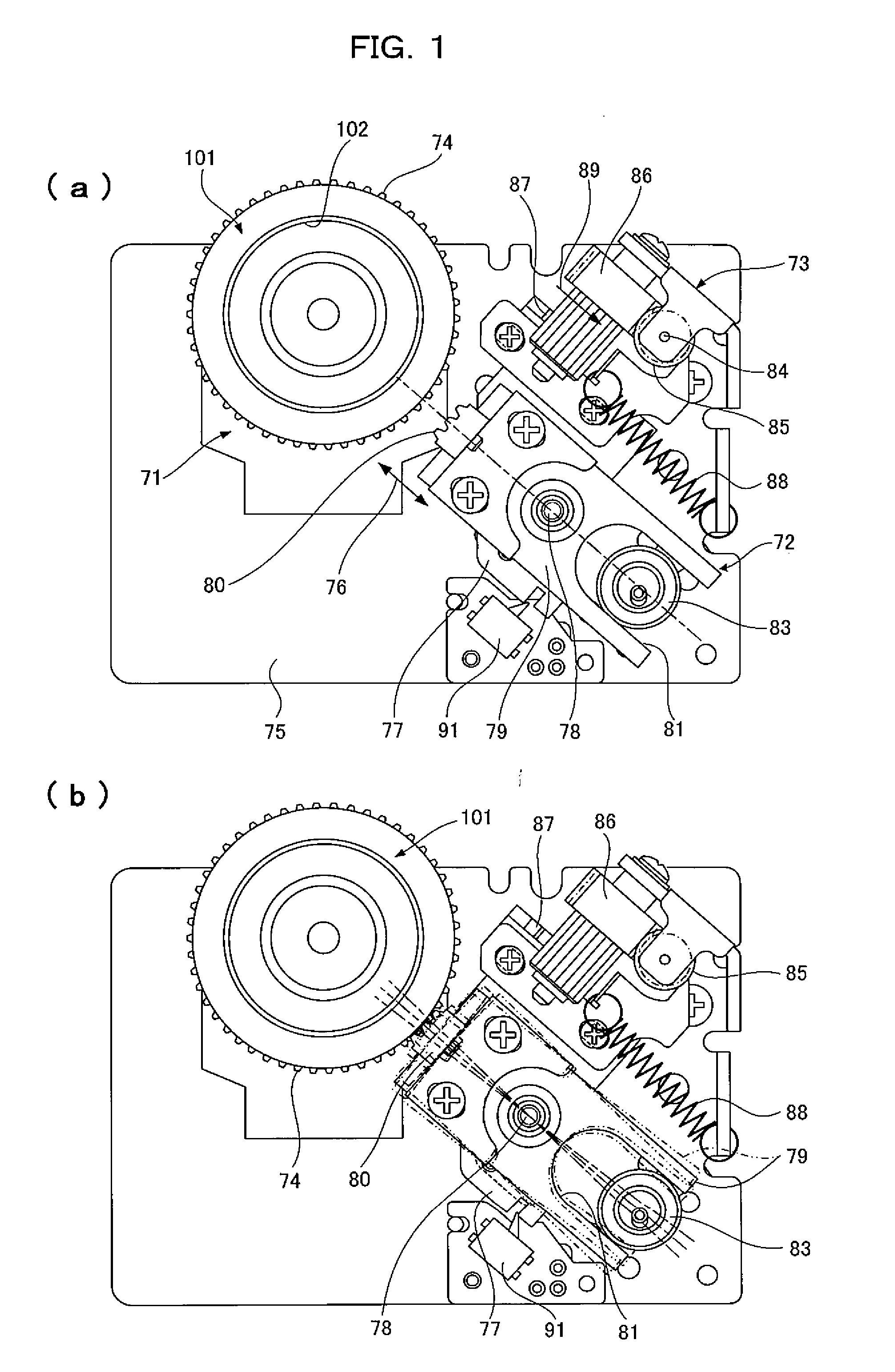
[0083]FIGS. 1 to 10 show an analyzing apparatus according to a first embodiment of the present invention.
[0084]FIGS. 8 to 10 show an analyzing device.
[0085]FIGS. 8(a) and 8(b) show an analyzing device 1 with an opened and closed protective cap 2. FIG. 9 is an exploded view of the analyzing device 1 with the underside of FIG. 8(a) placed face up. FIG. 10 is an assembly drawing of FIG. 8(b).
[0086]The analyzing device shown in FIGS. 8 and 9 is made up of four components of a base substrate 3 having a microchannel structure formed on one surface, the microchannel structure having a minutely uneven surface, a cover substrate 4 for covering the surface of the base substrate 3, a diluent container 5 for retaining a diluent, and the protective cap 2 for preventing splashes of a sample liquid.
[0087]The base substrate 3 and the cover substrate 4 are joined to each other with the diluent container 5 and so on set in the base substrate 3 and the cover substrate 4, and the protective cap 2 is at...
second embodiment
[0112]FIGS. 11 and 12 show a second embodiment of the present invention.
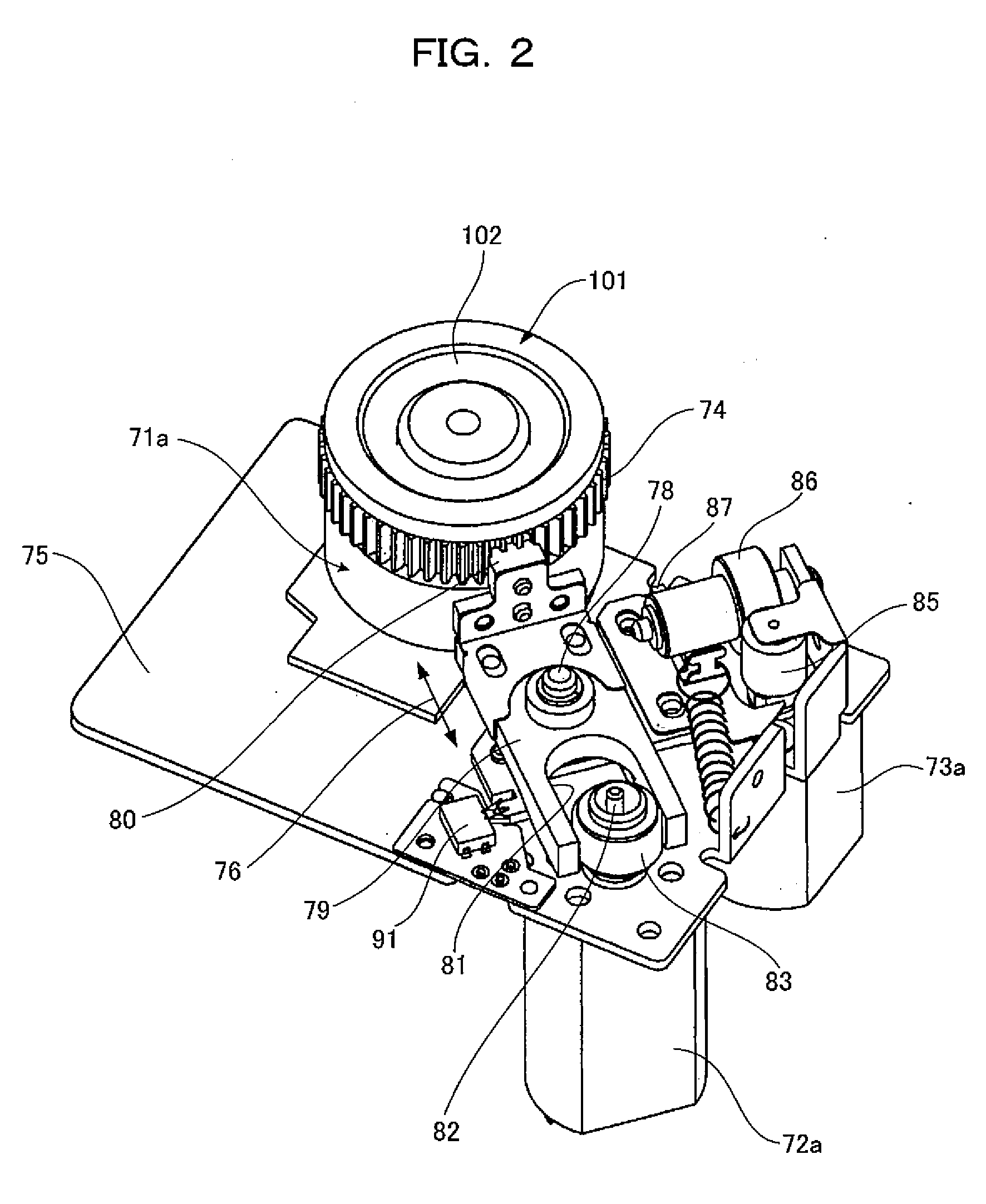
[0113]In the rotational drive section 106 of the first embodiment, the analyzing device is reciprocated by swingingly driving the second drive part in the tangential direction of the turntable. The second embodiment of FIGS. 11 and 12 is different in that a second drive part is reciprocated in the tangential direction of a turntable. Another different point is that the driving source of a third drive part is a solenoid.
[0114]Regarding the different points from the first embodiment, the operations will be specifically described below.
[0115]As shown in FIGS. 11 and 12, a second motor 72a, a solenoid 204, support shafts 203a and 203b, a support shaft 209, and the like are attached to a chassis 75 where a first motor 71a has been attached.
[0116]On the support shafts 203a and 203b, a lever 201 is slidably pivoted by a spacer 210 and fasteners 212. On the side of the turntable 101a, the lever 201 has a side bent in pa...
third embodiment
[0124]The control section 109 of the first, second, and third motors 71a, 72a, and 73a of the first embodiment is configured as will be described below. Thus even when the tops of the teeth of a second gear 80 and the tops of the teeth of a first gear 74 collide each other, the tops of the teeth of the second gear 80 can be reliably engaged with the bottoms of the teeth of the first gear 74, achieving stable mixing and agitation for an analyzing device 1.
[0125]In the case where signals are outputted from the control section 109 to the first motor 71a, the second motor 72a, and the third motor 73a during mixing and agitation as indicated by (a), (b), and (c) in FIG. 13, the control section 109 is configured as shown in FIG. 14.
[0126]To be specific, when the control section 109 detects an instruction of agitation / mixing during the stop period of the first motor 71a, the control section 109 starts energizing the second motor 72a before energizing the third motor 73a to make a forward r...
PUM
 Abstract
Description
Claims
Application Information
 - R&D
- Intellectual Property
- Life Sciences
- Materials
- Tech Scout
- Unparalleled Data Quality
- Higher Quality Content
- 60% Fewer Hallucinations
Browse by: Latest US Patents, China's latest patents, Technical Efficacy Thesaurus, Application Domain, Technology Topic, Popular Technical Reports.
© 2025 PatSnap. All rights reserved.Legal|Privacy policy|Modern Slavery Act Transparency Statement|Sitemap|About US| Contact US: help@patsnap.com


