
Blood fluidity measurement system and blood fluidity measurement method

a blood fluidity and measurement system technology, applied in the direction of indirect flow property measurement, instruments, image enhancement, etc., can solve the problem of measurement taking a lot of time, and achieve the effect of blood fluidity and blood fluidity measurement in a short tim

Inactive Publication Date: 2010-10-14
KONICA MINOLTA OPTO
View PDF7 Cites 8 Cited by
  • Summary
  • Abstract
  • Description
  • Claims
  • Application Information

AI Technical Summary

Benefits of technology

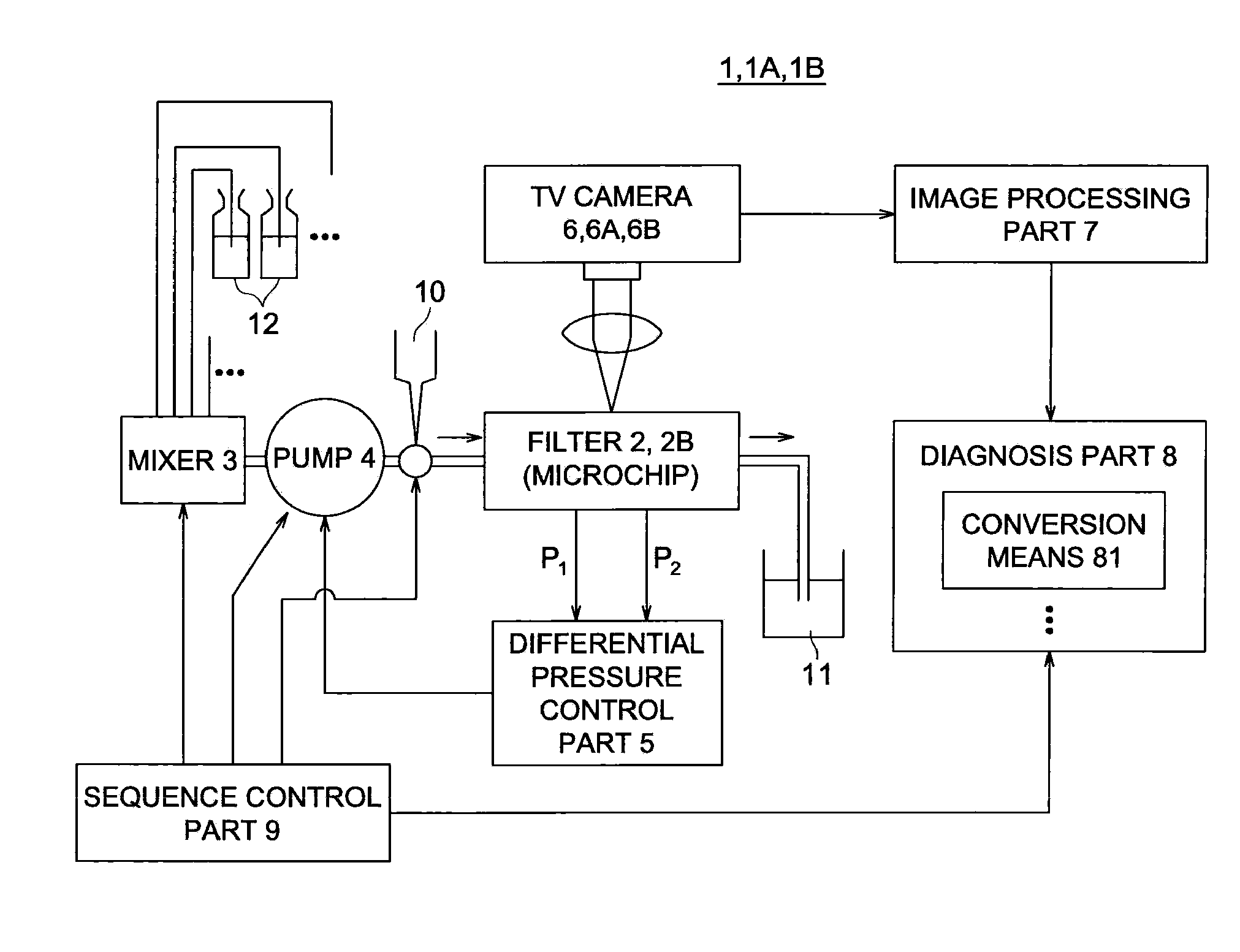
[0019]According to the invention described in claim 1, since there are provided a means of taking a picture, which takes a picture of blood flow in a channel, and a detection means for the state of blood flow to detect as blood fluidity the state of blood flow in the above channel from an image obtained by the means of a taking picture, the blood fluidity can be detected at any time, if the image is timely taken by the above means of taking a picture. Therefore, compared to a conventional case, in which the time taken for a prescribed amount of blood to fully pass through a filter was measured, the blood fluidity can be measured in a short time.

Problems solved by technology

However, with the method described in Patent Document 1, it is required to measure the time taken for a prescribed amount of blood to fully pass through a filter, and the measurement takes a lot of time.

Method used


Image

  • Blood fluidity measurement system and blood fluidity measurement method
  • Blood fluidity measurement system and blood fluidity measurement method
  • Blood fluidity measurement system and blood fluidity measurement method

Examples


first modified example

the Embodiment

[0082]Subsequently, the first modified example of the blood fluidity measurement system 1 will be described. Any constituent element similar to the above embodiment will be denoted by the same reference numerals, and their descriptions will be omitted.

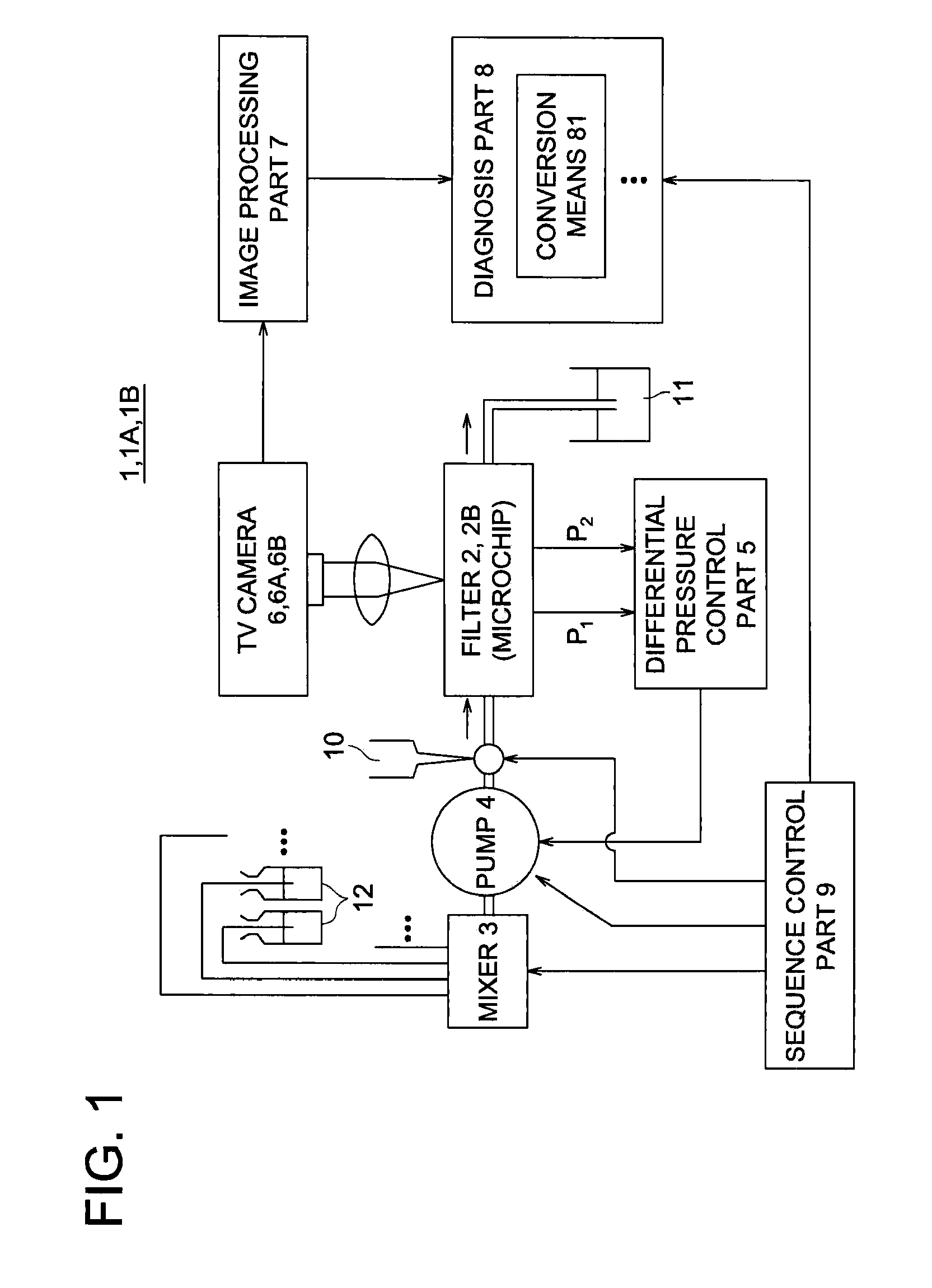
[0083]A blood fluidity measurement system 1A is, as shown in FIG. 1, provided with a TV camera 6A in place of the TV camera 6 in the above-described embodiment. The TV camera 6A is a camera for taking moving pictures with a frame rate of 30 fps.

[0084]A blood fluidity measurement method via the above blood fluidity measurement system 1A will be described.

[0085]First, steps until a step of taking a picture of blood flow after blood is flowed in the filter 2 are similar to those described in the above-described embodiment. However, in this modified example, even if the speed of blood flowing the gate 30 is 2.46 to 14.7 μm / ms, which is the same as that of the above-described embodiment, because of the frame rate of the TV cam...

second modified example

the Embodiment

[0100]Subsequently, a blood fluidity measurement system 1B as the second modified example of the blood fluidity measurement system 1 will be described. Any constituent element similar to the above embodiment will be denoted by the same reference numerals, and their descriptions will be omitted.

[0101]The blood fluidity measurement system 1B is, as shown in FIG. 1, provided with a microchip 2B in place of the filter 2, and a TV camera 6B in place of the TV camera 6 in the above-described embodiment.

[0102]The microchip 2B is, as shown in FIG. 11, formed by stacking a rectangular glass flat board 20B and a base board 21B.

[0103]The glass flat board 20B is formed in a flat board fashion, and covers an interior surface (the upper surface of FIG. 11b) of the base board 21B.

[0104]The base board 21B has hollow parts 210B and 211B at each end, and a plurality of grooves 212B and others between the above hollow parts 210B and 211B.

[0105]Of these hollow parts, the hollow part 210B ...


PUM


Abstract

Blood fluidity is measured in a short time. A blood fluidity measurement system, which measures blood fluidity by flowing blood into a channel, is equipped with a TV camera which photographs the blood stream in the channel and an image processing part which detects the state of the blood stream in the channel as blood fluidity from the image taken by the TV camera.

Description

TECHNICAL FIELD[0001]The present invention relates to a blood fluidity measurement system and a blood fluidity measurement method.BACKGROUND TECHNOLOGY[0002]In recent years, along with increasing awareness of health, blood fluidity has been paid attention as a health barometer. The fluidity is also called as the degree of smoothness, and it means that the higher the fluidity or the smoothness, the better in health.[0003]As a method for investigating the above blood fluidity, it has been known that, as described for example in Patent Document 1, blood is allowed to pass through a filter with fine grooves, and the time required for passing through the filter is measured. Further, it is also possible for the method of Patent Document 1 to grasp visually the blood fluidity by observing with a camera blood cells passing through the filter using a filter substrate made of a transparent glass.[0004]Patent Document 1: Japanese Patent No. 2685544DISCLOSURE OF INVENTIONIssues to be Solved by ...

Claims


Application Information

Patent Timeline
IPC IPC(8): G06K9/00
CPCG01N11/06G01N11/08G01N35/1097G01N2011/008G01N2015/0073G06T2207/30104G01N2015/1075G01N2015/1495G06T7/0012G06T2207/10016G01N2015/0092G01N2015/012G01N2015/1027
Inventor ICHITANI, SHUJITAKAMA, MASAAKIMURAYAMA, TAKANORI
Owner KONICA MINOLTA OPTO
Learn More