Display system, control system, and display method

a control system and display method technology, applied in the field of display systems and control systems, can solve problems such as deterioration of brightness, increase of power consumption, and security and privacy, and achieve the effect of high speed

Inactive Publication Date: 2010-10-14
NEC CORP
View PDF2 Cites 12 Cited by
  • Summary
  • Abstract
  • Description
  • Claims
  • Application Information

AI Technical Summary

Benefits of technology

[0026]The present invention can brighten the images by decreasing or without increasing the driving frequency of a controller and a driver which control the display when displaying a plurality of images while switching those at a high speed.BEST MODES FOR CARRYING OUT THE INVENTION
[0169]The present invention makes it possible to achieve plural image display which allows recognition of specific images only to the user of a high-definition panel that displays the images, a notebook personal computer, a portable terminal, a portable telephone, and the like with a relatively low driving frequency. Therefore, the present invention exhibits the applicability in a wide range of fields such as the fields of the information processor terminal, information communication, and the like.

Problems solved by technology

Under such environments, there are issues regarding security and privacy, i.e., displayed contents on the display can be recognized by people around.
However, there are issues in the above-described methods disclosed in Patent Document 2 or Patent Document 3.
Driving with such high frequency induces an increase of the power consumption.
This results in causing an issue of deteriorating the brightness.
Even if a dot clock is simply increased for shortening the writing period further, the writing period cannot be shortened.
Signal input time for the pixels is rate-determined with the data line wiring delay at the time of normal signal input, so that it is difficult to achieve driving with high frequency.
Therefore, Patent Document 3 has the same issues in terms of the fact that the power consumption is increased and the driving becomes difficult.

Method used


Image

  • Display system, control system, and display method
  • Display system, control system, and display method
  • Display system, control system, and display method

Examples


first exemplary embodiment

[0050]A case of using the pixel electrode parts of a liquid crystal panel and an organic EL panel, for example, as the pixels of the display screen of the exemplary embodiments of the invention will be described as a first exemplary embodiment of the invention. A case of the liquid crystal panel will be described in particular.

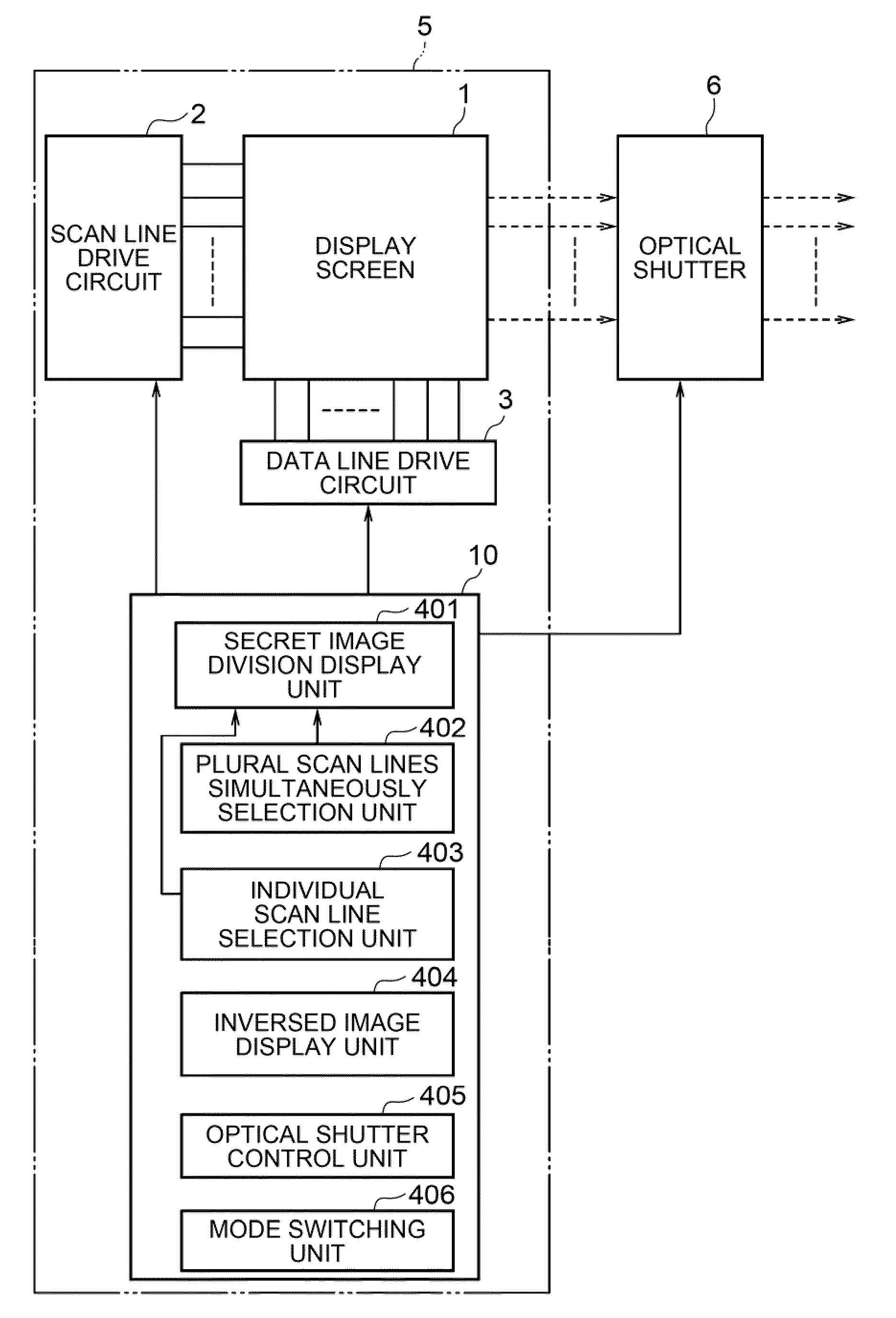
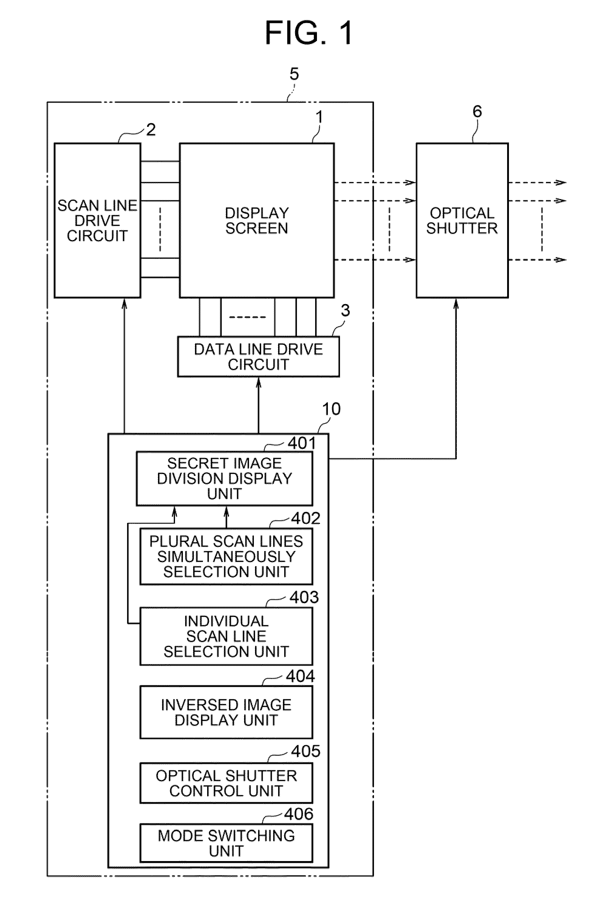
[0051]As shown in FIG. 1, a display system. 5 according to the first exemplary embodiment of the invention has a display screen 1 configured with a plurality of pixels that are arranged in matrix or in a form conforming to that, and a controller 10 which controls sequentially repeated display of two or more types of images. An optical shutter 6 that is opened and closed by synchronizing with the display of images is provided as necessary. The optical shutter 6 is drive-controlled by the controller 10.

[0052]As shown in FIG. 4, the pixels of the display screen 1 shown in FIG. 1 are provided by corresponding to each of the intersections between n-number of scan l...

second exemplary embodiment

[0061]Next, a case of using the phosphor part of a CRT or a projected part of a laser projector as the pixels of the display screen 1 according to the exemplary embodiment of the invention will be described as a second exemplary embodiment of the invention. Hereinafter, the display screen 1 is expressed as a projection panel 12, including the phosphor part and the projected part.

[0062]As shown in FIG. 3A, normally, when a single electron beam or a laser beam (hereinafter, generally called laser beam) 14 is emitted from an radiation part 11 with an intensity corresponding to image data to have the laser beam 18 radiated as a spot on the projection panel 12, an irradiated position 15 emits light. The laser beam 18 is scanned and the irradiated position 15 is shifted along a single scan line 16 as shown in FIG. 3B. After scanning the single scan line 16, a next scan line 16 is scanned in the same manner to display an image. This operation is repeated to display two or more images seque...

third exemplary embodiment

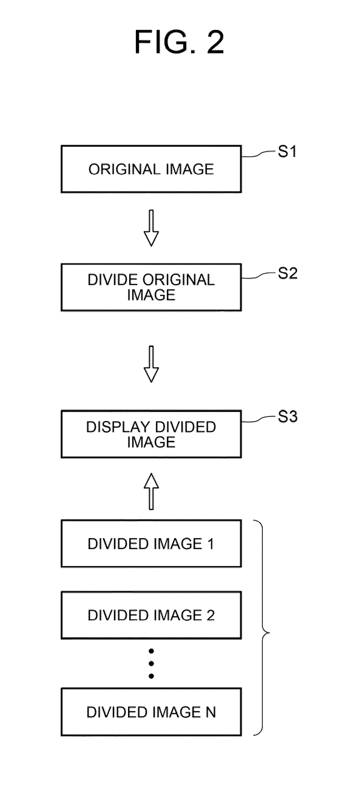
[0064]Next, in regards to the first exemplary embodiment of the invention, a display method which creates the original image, i.e., regenerates the original image, through dividing the original image into two divided images and sequentially displaying the two divided images will be described as a third exemplary embodiment of the invention.

[0065]FIG. 7A shows a state of writing a first divided image, and FIG. 7B shows a state of writing a second divided image.

[0066]In FIG. 7A, when writing the first divided image, the controller 10 controls the scan line drive circuit 2 to select k-number of scan lines 7 simultaneously from a plurality of scan lines 7. Specifically, in FIG. 7A, k-number of scan lines 7 on the rows of row numbers from “1” to “k” are selected simultaneously. Those simultaneously selected scan lines are expressed as “441”. Then, the controller 10 controls the data line drive circuit 3 to write the image data of the first divided image to the pixels 9 corresponding to t...


PUM


Abstract

To provide a display device which can reduce driving frequency of a controller and a driver for inputting a signal to the display device and increase brightness of a screen without increasing the driving frequency. The display device includes: a display screen having a plurality of pixels provided by corresponding to intersection points between scan lines and data lines; a scan line drive circuit which drives the scan lines; a data line drive circuit which drives the data lines; and a display device body having an image display control device which operates the drive circuit so as to sequentially and repeatedly display two or more types of images. The image display control device causes the scan line drive circuit to simultaneously select two or more scan lines for at least one type of image among the two or more types of images sequentially displayed.

Description

TECHNICAL FIELD[0001]The present invention relates to a display system, a control system, and a display method. More specifically, the present invention relates to a display system, a control system, and a display method, which display a plurality of images by switching those images at a high speed.BACKGROUND ART[0002]Currently, portable terminals such as notebook personal computers, personal digital assistances (PDAs), and portable telephones are used daily at places where other people are around, e.g., on vehicles such as trains and airplanes, and various public facilities. It is expected that such trends will accelerate further in the future in accordance with increases in public LAN equipment caused due to developments of a ubiquitous information society. Under such environments, there are issues regarding security and privacy, i.e., displayed contents on the display can be recognized by people around. Further, there is an increasing tendency to enhance protection of confidentia...

Claims


Application Information

Patent Timeline
Patent Type & Authority Applications(United States)
IPC IPC(8): G09G5/00
CPCG06F21/84G09G3/20G09G3/2018H04N2013/0463G09G2310/0267G09G2320/0626H04N13/0438G09G2310/0205H04N13/341H04N2013/403
Inventor KIMURA, KAZUNORIIMAI, MASAO
Owner NEC CORP
Why Eureka
Try Eureka