Short-pulse light source, laser light emitting method, optical device, optical disk device, and light pickup

a laser light emitting and light pickup technology, applied in the field laser light emission methods, optical devices, optical disc devices, etc., can solve the problems of unpractical mounting of short-pulse light sources in optical disc devices, large size of short-pulse light sources, and high pri

Inactive Publication Date: 2010-10-07
SONY CORP
View PDF5 Cites 3 Cited by
  • Summary
  • Abstract
  • Description
  • Claims
  • Application Information

AI Technical Summary

Benefits of technology

[0012]Also, in a laser light emission method according to the present invention, a pulse width of a pulse-shaped drive voltage pulse is controlled when specific output light having a pulse-shaped specific peak and a specific slope is caused to be emitted as laser light, an emission intensity of the specific slope being lower than an emission intensity of the specific peak, by applying a laser drive voltage having the drive voltage pulse to a semiconductor laser, whereby a ratio between the specific peak and the specific slope is adjusted.
[0014]Furthermore, an optical disc device and an optical pickup according to the present invention are provided with a semiconductor laser configured to emit laser light, an objective lens configured to irradiate an optical information recording medium with the laser light, and a laser control unit configured to control a pulse width of a pulse-shaped drive voltage pulse when causing specific output light having a pulse-shaped specific peak and a specific slope to be emitted as the laser light, an emission intensity of the specific slope being lower than an emission intensity of the specific peak, by applying a laser drive voltage having the drive voltage pulse to the semiconductor laser, thereby adjusting a ratio between the specific peak and the specific slope.
[0017]Accordingly, in the present invention, switching between oscillation output light and specific output light can be freely performed using a rise of a drive voltage pulse.
[0018]Furthermore, an optical disc device according to the present invention is provided with a semiconductor laser configured to emit laser light having a first wavelength by being applied with a laser drive voltage that is lower than an oscillation voltage value for causing relaxation oscillation, an irradiation unit configured to irradiate an optical information recording medium with the laser light, and a laser control unit configured to control a rise of a pulse-shaped drive voltage pulse when applying a laser drive voltage having the drive voltage pulse to the semiconductor laser, thereby causing oscillation output light generated by relaxation oscillation to be emitted as the laser light during a reproduction process and causing specific output light having a wavelength in the vicinity of the first wavelength and a second wavelength shorter than the first wavelength to be emitted as the laser light during a recording process.
[0019]Accordingly, in the present invention, switching between oscillation output light and specific output light can be freely performed using a rise of a drive voltage pulse.

Problems solved by technology

Therefore, the short-pulse light source typically has a large size and a high price, and thus mounting it in an optical disc device is unpractical.

Method used


Image

  • Short-pulse light source, laser light emitting method, optical device, optical disk device, and light pickup
  • Short-pulse light source, laser light emitting method, optical device, optical disk device, and light pickup
  • Short-pulse light source, laser light emitting method, optical device, optical disk device, and light pickup

Examples


first embodiment

(1) First Embodiment

(1-1) Configuration of Short-Pulse Light Source

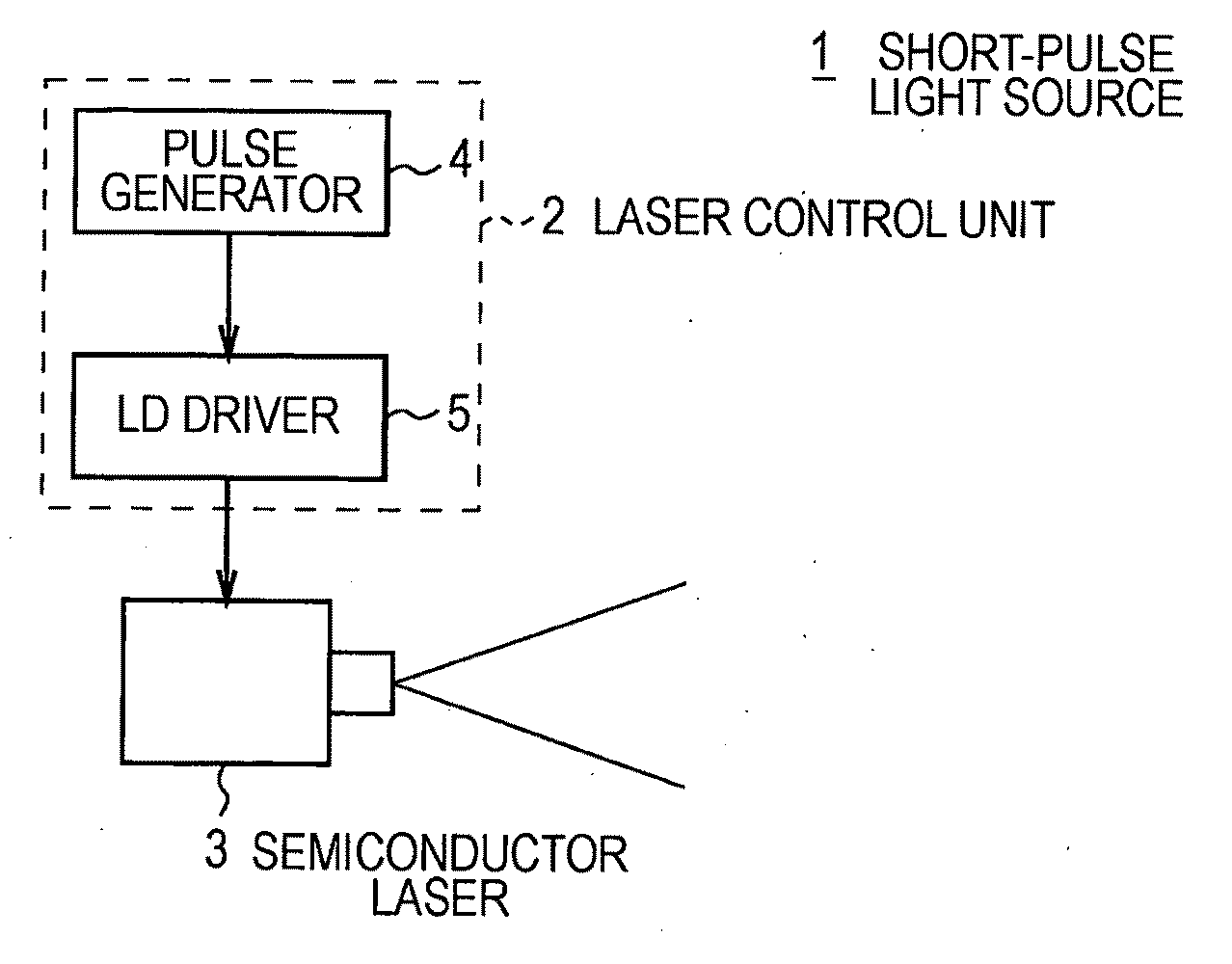
[0062]In FIG. 1, reference numeral 1 denotes an entire short-pulse light source according to this embodiment. The short-pulse light source 1 includes a laser control unit 2 and a semiconductor laser 3.

[0063]The semiconductor laser 3 is a typical semiconductor laser that uses semiconductor emission (e.g., SLD3233 made by Sony Corporation). The semiconductor laser 3 is configured to output laser light LL in a pulsed manner through a drive voltage control process (details will be described below) performed by the laser control unit 2.

[0064]The laser control unit 2 includes a pulse generator 4 and an LD (Laser Diode) driver 5. As illustrated in part (A) of FIG. 2, the pulse generator 4 generates a pulse signal SL in which pulse-shaped generated signal pulses SLw are discretely generated, and supplies the pulse signal. SL to the LD driver 5. At this time, the pulse generator 4 controls the signal level of the generated si...

second embodiment

(2) Second Embodiment

[0166]In the second embodiment illustrated in FIGS. 29 to 38, the parts corresponding to those in the first embodiment illustrated in FIGS. 1 to 28 are denoted by the same reference numerals. The second embodiment is different from the first embodiment in that a short-pulse light source 120 corresponding to the short-pulse light source 1 is used in an optical disc device 110.

[0167](2-1) Configuration of Optical Disc

[0168]First, a configuration of an optical disc 100 will be described. In this embodiment, information is recorded on the optical disc 100 by irradiating the optical disc 100 with an information light beam LM serving as laser light LL emitted from the optical disc device 110. Also, information is read from the optical disc 100 by detecting a reflected information light beam LMr, which is generated when the information light beam LM is reflected.

[0169]Actually, the optical disc 100 is substantially disc-shaped as a whole, and a hole portion 100H for ch...


PUM

PropertyMeasurementUnit
emission start time τdaaaaaaaaaa

Abstract

The present invention can control output of pulses from a semiconductor laser.In the present invention, a short-pulse light source (1) applies a laser drive voltage (DJ) having a pulse-shaped drive voltage pulse (DJw) to a semiconductor laser (3), thereby causing the semiconductor laser (3) to emit specific output light (LAp), as laser light (LL), having a pulse-shaped specific peak (APK) and a specific slope (ASP), an emission intensity of the specific slope (ASP) being lower than an emission intensity of the specific peak (APK). The short-pulse light source (1) controls a voltage pulse half-width (Thalf), which is a pulse width of the drive voltage pulse (DJw), by setting a pulse width (Ws) of a set pulse (SLs), thereby adjusting a ratio between the specific peak (APK) and the specific slope (ASP).

Description

TECHNICAL FIELD[0001]The present invention relates to a short-pulse light source, a laser light emission method, an optical device, an optical disc device, and an optical pickup. For example, the present invention is preferably applied to an optical disc device in which information is recorded using light beams.BACKGROUND ART[0002]Conventionally, disc-shaped optical information recording media have been widely used as optical information recording media, and CDs (Compact Discs), DVDs (Digital Versatile Discs), Blu-ray Discs (registered trademark, hereinafter called Bps), and the like are generally used.[0003]On the other hand, in an optical disc device compatible with such optical information recording media, various types of content, such as music content and video content, or various types of information, such as various data for a computer, is recorded on an optical information recording medium. Particularly, in recent years, the amount of information has been increasing due to h...

Claims


Application Information

Patent Timeline
Patent Type & Authority Applications(United States)
IPC IPC(8): G11B20/10H01S3/10
CPCB82Y10/00G11B7/00451G11B7/126H01S5/06216H01S5/0014H01S5/0428G11B2007/0009
Inventor FUJITA, GORO
Owner SONY CORP
Why Eureka
Try Eureka