
Illumination device for multineedle sewing machine and the multineedle sewing machine

a multi-needle sewing machine and needle thread technology, applied in the direction of lighting support devices, transportation and packaging, transportation and packaging, etc., can solve the problems of devices preventing needle thread hooking or needle exchange, and achieve the effect of preventing the illumination member from hindering the hooking of needle thread

Active Publication Date: 2010-09-30
BROTHER KOGYO KK
View PDF3 Cites 9 Cited by
  • Summary
  • Abstract
  • Description
  • Claims
  • Application Information

AI Technical Summary

Benefits of technology

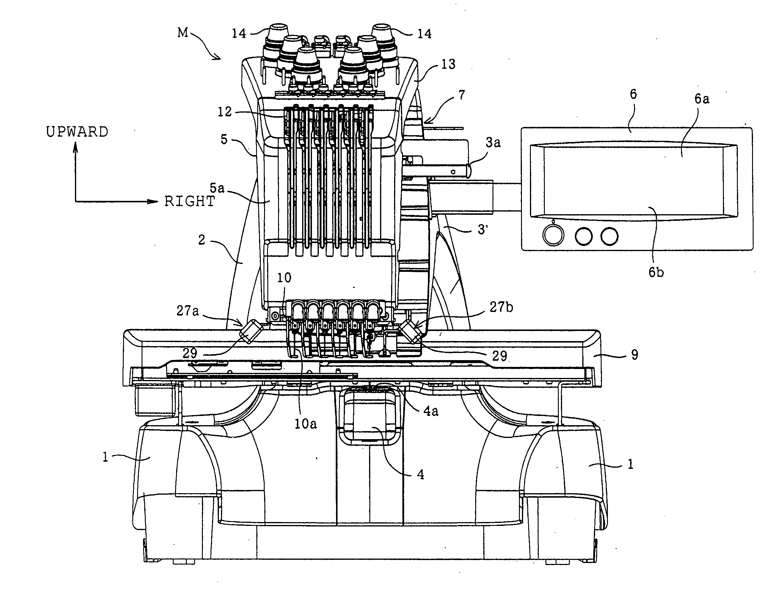
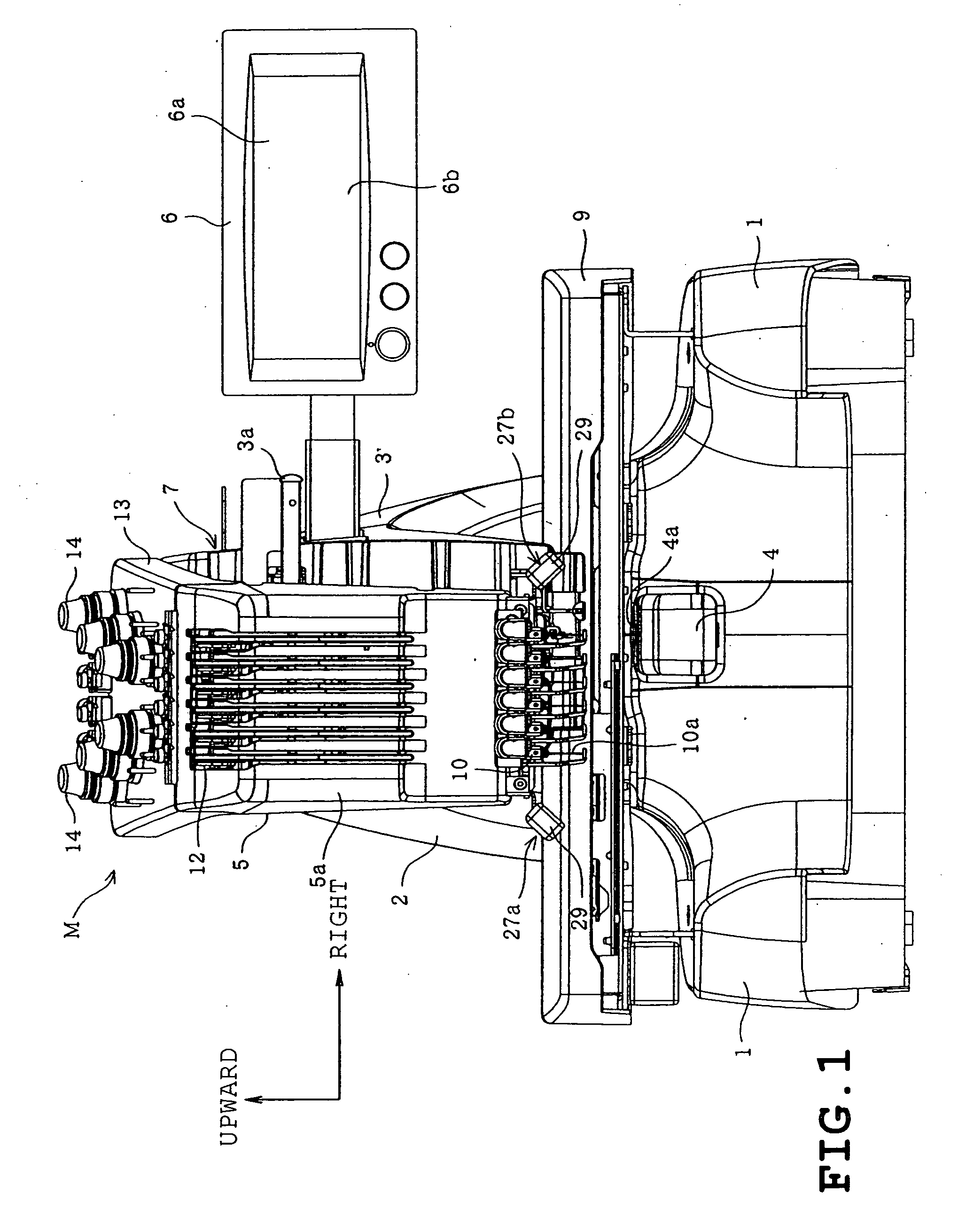
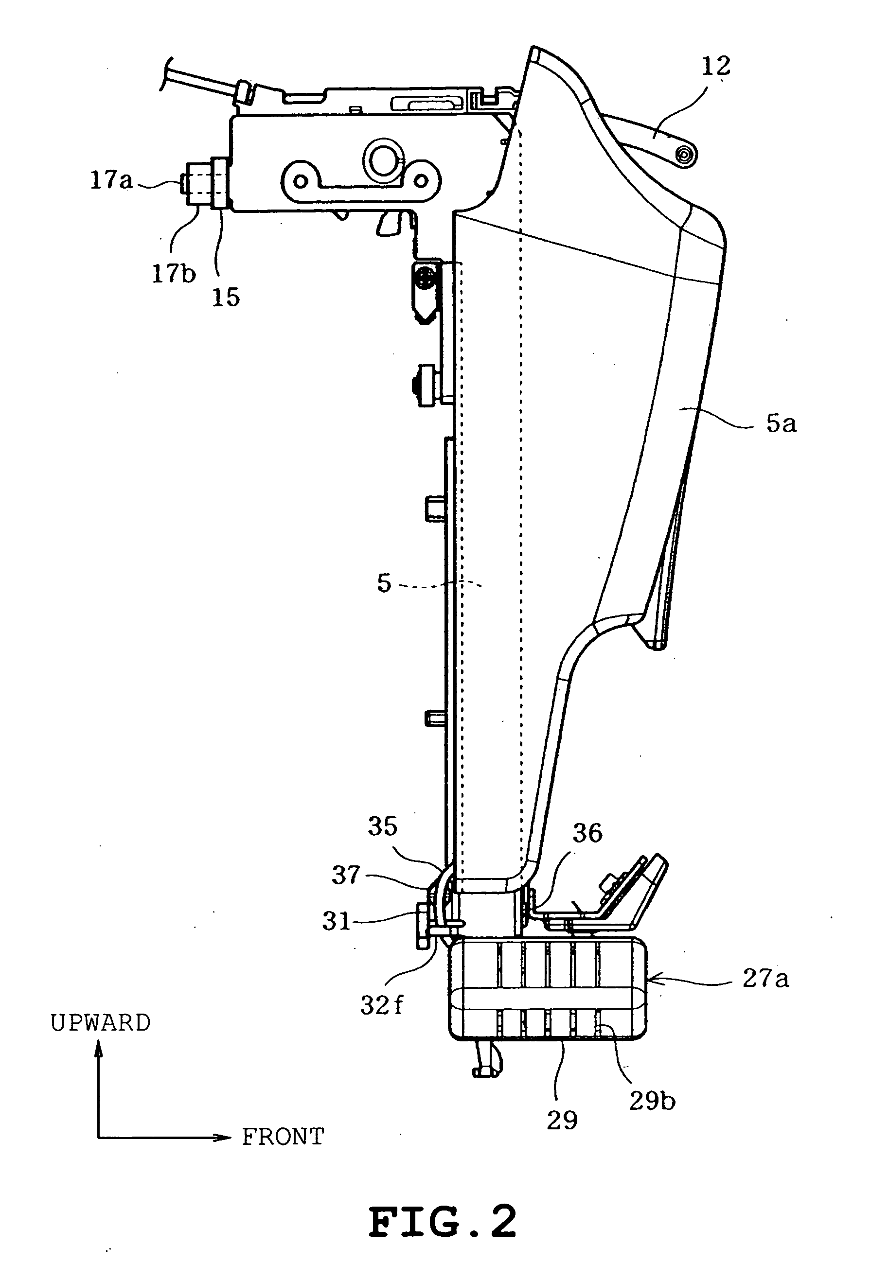
[0009]Therefore, an object of the present disclosure is to provide an illumination device for a multineedle sewing machine, in which an illuminating member can be prevented from hindering the hooking of needle thread or the like and a predetermined illuminance can be maintained at the needle drop position irrespective of movement of the needle bar case.

Problems solved by technology

Accordingly, each type of the above-described multineedle sewing machine has a problem that the illumination device hinders the hooking of needle thread or exchange of needles.

Method used


Image

  • Illumination device for multineedle sewing machine and the multineedle sewing machine
  • Illumination device for multineedle sewing machine and the multineedle sewing machine
  • Illumination device for multineedle sewing machine and the multineedle sewing machine

Examples


first embodiment

[0064]The upper mount 52, lower mount 33, connecting portion 55 and support bar 53 serve as a support member 57 which supports the illuminator 27a so that the illuminator 27a is swingable between the illuminating position and the retreat position. Furthermore, the support member 57 and the torsion coil spring 56 constitute the first support mechanism 51. The description of the right first support mechanism 51′ will be eliminated since the first support mechanism 51′ has the same structure as the left first support mechanism 51 and is disposed so as to be substantially bilaterally symmetrical to the left first support mechanism 51 about the center line L1 as in the

second embodiment

[0065] the illuminators 27a and 27b can be swung by the first support mechanisms 51 and 51′ between the illuminating position where the illumination area is illuminated by the LEDs 43 and the retreat position differing from the illuminating position. Accordingly, as shown in FIG. 11B, when the illuminators 27a and 27b are subjected to an external force during the thread hooking, the illuminators 27a and 27b can be escaped to the retreat position so as not to hinder the thread hooking. Consequently, the user need not return the illuminators 27a and 27b to the illuminating position.

[0066]FIGS. 12 to 15 illustrate a third embodiment. Identical or similar parts in the third embodiment are labeled by the same reference symbols as those in the first embodiment, and only the difference between the first and third embodiments will be described. The description of the right illuminator 61b will be eliminated since the right illuminator 61b has the same structure as the left illuminator 61a a...


PUM


Abstract

An illumination device for a multineedle sewing machine includes an illuminating member which has a light source and located at a lateral side of a needle bar case and is disposed so as to open portions of needle bars and portions of needles, a light amount adjusting unit which adjusts an amount of light of the light source, and a control unit which controls the light amount adjusting unit with movement of the needle bar case by the needle bar case moving mechanism together with the illuminating member so that a predetermined illuminance is maintained at least in part of an illuminated area which is illuminated by the light source. The part of the illuminated area is located near the needle drop position.

Description

CROSS-REFERENCE TO RELATED APPLICATIONS[0001]This application is based on and claims the benefit of priority from the prior Japanese Patent Application No. 2009-79169, filed on Mar. 27, 2009, the entire contents of which are incorporated herein by reference.BACKGROUND[0002]1. Field[0003]The present disclosure relates to an illumination device for a multineedle sewing machine provided with a plurality of needle bars having lower ends to which needles are attached, respectively, a needle bar case which supports the needle bars so that the needle bars are movable upward and downward and a needle bar case moving mechanism which selectively switches one of the needle bars to a needle drop position, and the multineedle sewing machine provided with the illumination device.[0004]2. Related Art[0005]There have conventionally been provided multineedle sewing machines of the above-described type which include an illumination device for illuminating a needle base of each needle or a surface of ...

Claims


Application Information

Patent Timeline
IPC IPC(8): D05B79/00
CPCD05B79/00
Inventor FUJIHARA, SHINYAISHIYAMA, YASUHIROMATSUMOTO, NOBUAKIMATSUDA, JUNNOSUKE
Owner BROTHER KOGYO KK
Learn More