Scroll fluid machine

a fluid machine and scrolling technology, applied in the direction of liquid fuel engines, positive displacement liquid engines, piston pumps, etc., can solve the problems of difficult to secure offset thrust loads acting on the right and left orbiting scrolls

Inactive Publication Date: 2010-09-23
ANEST IWATA CORP
View PDF2 Cites 2 Cited by
  • Summary
  • Abstract
  • Description
  • Claims
  • Application Information

AI Technical Summary

Benefits of technology

[0006]In view of the disadvantages, it is an object of the invention to provide a scroll fluid machine that responds to difference in AC frequency and voltage, thrust acting to right and left orbiting scrolls being efficiently offset.

Problems solved by technology

It would be very difficult to offset thrust loads acting the right and left orbiting scrolls securely.

Method used


Image

  • Scroll fluid machine
  • Scroll fluid machine
  • Scroll fluid machine

Examples


Embodiment Construction

[0012]One embodiment of the present invention will be described with respect to the drawings.

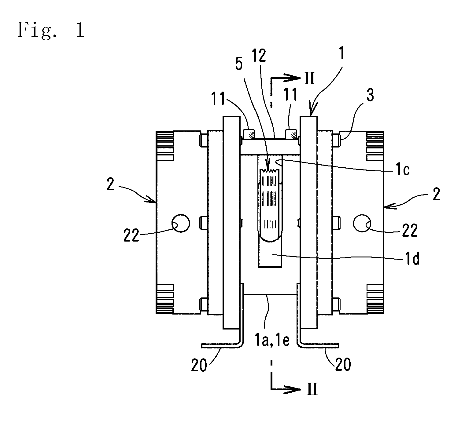
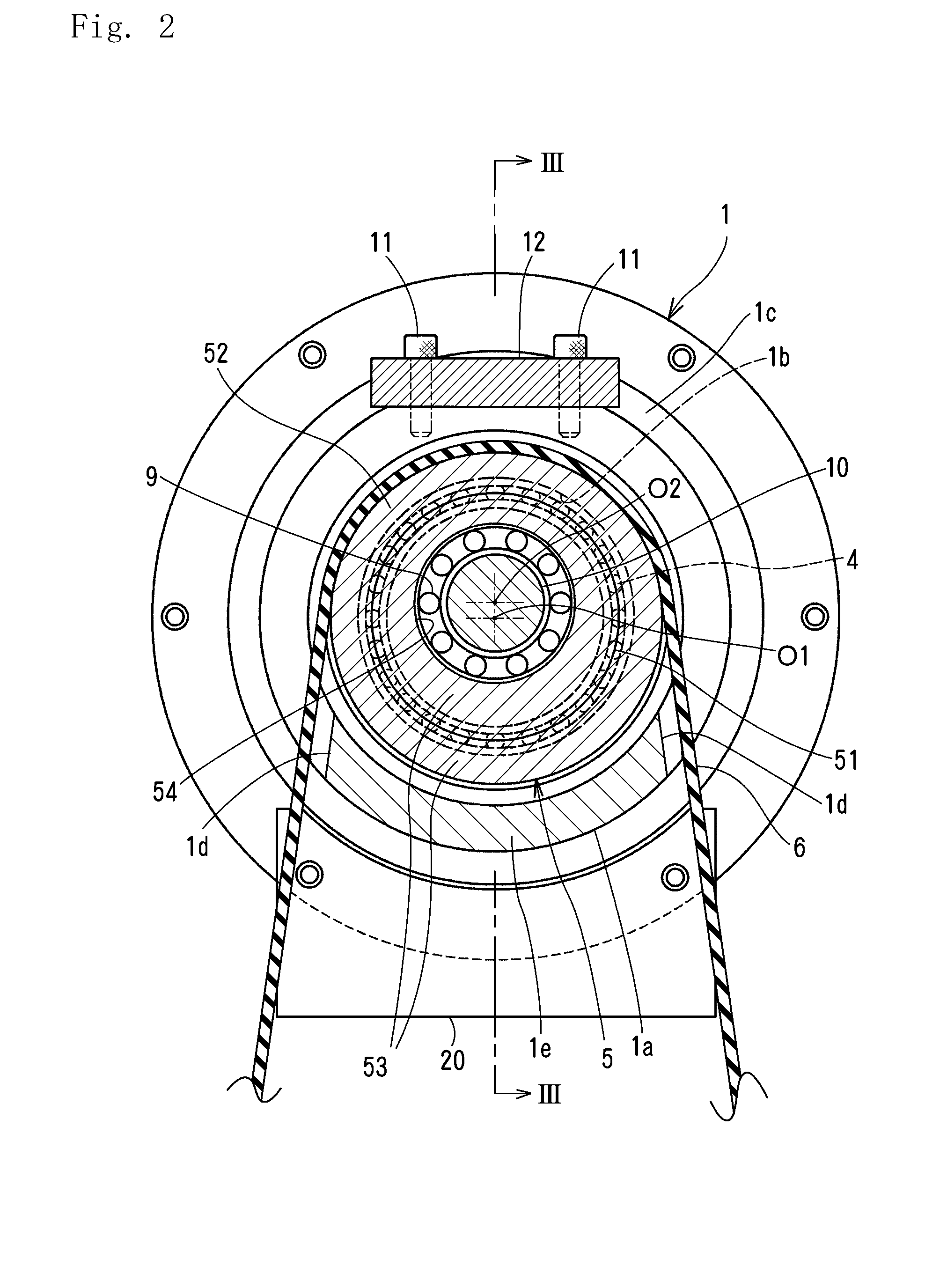
[0013]In FIGS. 1 and 3, at each side of a cylindrical housing 1 of a scroll fluid machine, a fixed scroll 2 which includes a fixed wrap 21 is fixed with a plurality of screws. L-shaped feet 20, 20 which are fixed on a support (not shown) are fixed to the lower part of the housing 1.

[0014]On the inner side surface of the fixed scroll 2, a spiral orbiting scroll 3 which has a spiral orbiting wrap 31 engages with the fixed wrap 21 to form a compression chamber so as to rotate around the first axis O1.

[0015]The right-hand orbiting scroll 2 is disposed on the inside of the housing 1 with three known pin-crank-type self-rotation preventing devices 30 spaced on a circle by 120 degrees. Only one of the self-rotation preventing devices is shown in FIG. 3. In this embodiment, the right and left orbiting scrolls 3, 3 are fixed at the right and left ends of a thrust offsetting shaft 10. Thus, the pin-cr...


PUM


Abstract

A scroll fluid machine comprises a housing, two fixed scrolls each of which is fixed on each side of the housing, an endless transmitting member connected to an electric motor, a driven pulley wound by the transmitting member, a thrust-offsetting shaft rotatably mounted at a position eccentric from a axis in the driven pulley, two orbiting scrolls each of which is fixed at each end of the thrust-offsetting shaft which rotates to form a compression chamber with the fixed scroll, and a self-rotation preventing device disposed between the housing and the orbiting scroll.

Description

BACKGROUND OF THE INVENTION[0001]The present invention relates to a scroll fluid machine suitable as an air compressor and a vacuum pump.[0002]In JP2000-130365A, a scroll fluid machine comprises a casing, a fixed scroll fixed at each side of the casing, an electric motor in the casing, an eccentric bearing disposed between the electric motor and the fixed scroll, a rotational shaft that rotates together with an intermediate wheel of the eccentric bearing with a rotor of the electric motor, an orbiting shaft that rotates together with an inner wheel of the eccentric bearing, an orbiting scroll fixed to the orbiting shaft to form a compression chamber with the fixed scroll at each side, and a self-rotation preventing device provided between the orbiting scroll and a stationary member.[0003]In JP2006-183561A, an orbiting scroll is rotatably supported on each end of a single eccentric shaft rotatably mounted in a casing. An eccentric shaft is connected to an electric motor via an endles...

Claims


Application Information

Patent Timeline
Patent Type & Authority Applications(United States)
IPC IPC(8): F04B35/04
CPCF04C18/0215F04C23/001F04C2240/52F04C29/0021F04C29/005F04C23/02
Inventor SATO, KAZUAKI
Owner ANEST IWATA CORP
Why Eureka
Try Eureka