
Boat lift

a technology for lifting boats and boats, applied in the direction of vertical ship lifting, waterborne vessels, construction, etc., can solve the problems of unsightly cables, unstable and functionally inefficient, drive mechanisms, etc., to reduce the effect of “swinging” effect, more stability, and clean lines

Inactive Publication Date: 2010-09-23
BROWN CURTIS
View PDF45 Cites 21 Cited by
  • Summary
  • Abstract
  • Description
  • Claims
  • Application Information

AI Technical Summary

Benefits of technology

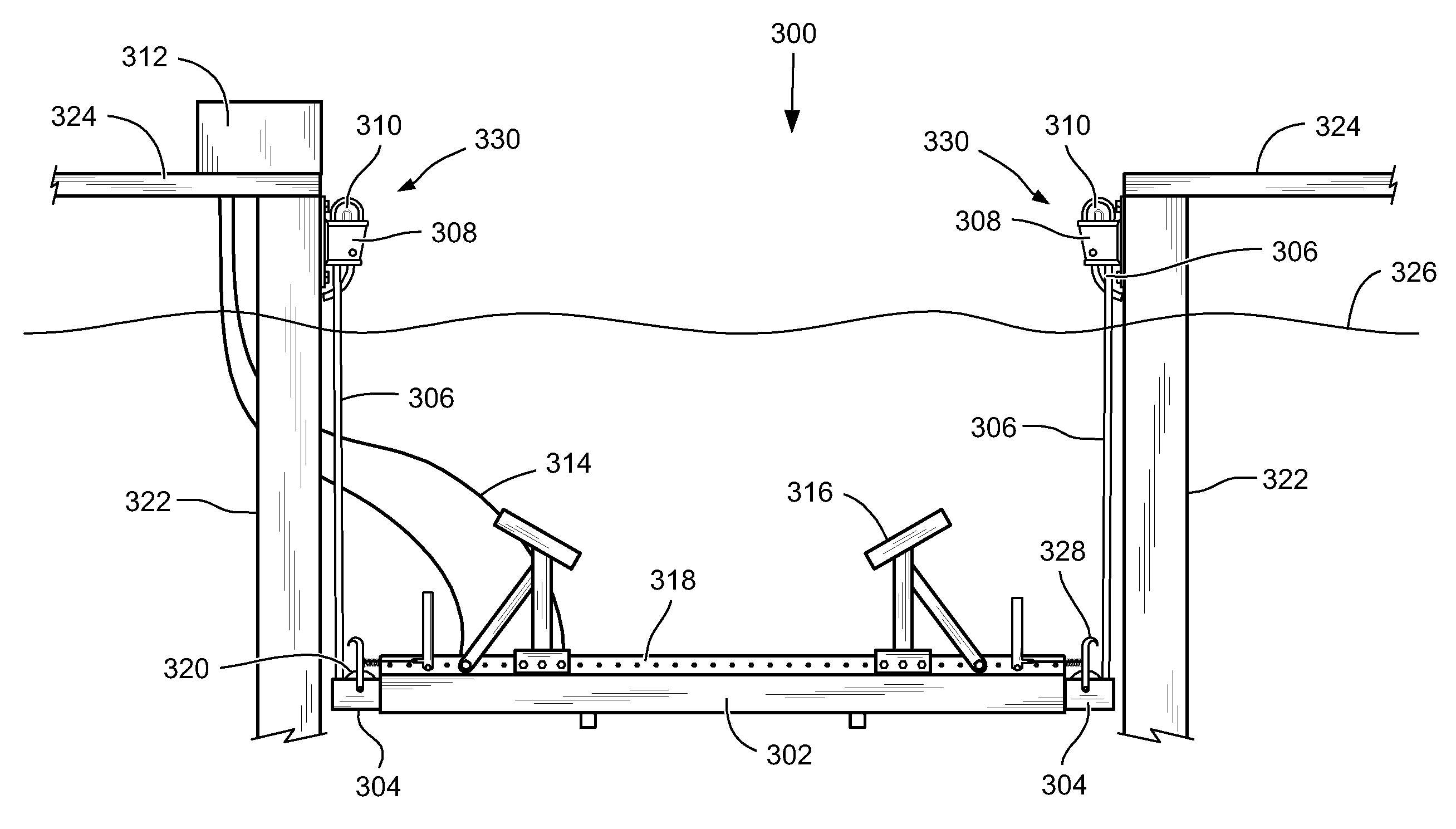
[0011]In this way, the present invention provides a cleaner, more aesthetically pleasing structure because as the boat is in a lifted position, the support cables are nearly unseen, as are the drive system components. Further, it provides more stability, because in a lifted configuration, less cable length exists between attachment or contact points, reducing a “swinging” effect most notably observed in prior art boat lifts. Still further, it provides a more self-contained and inclusive support and cable drive mechanism assembly, allowing more versatility in the positioning of the support beams along the length of a boat, and thus, applying the lifting force in a more balanced manner.

Problems solved by technology

However, they tend to be unsightly, unstable and functionally inefficient.
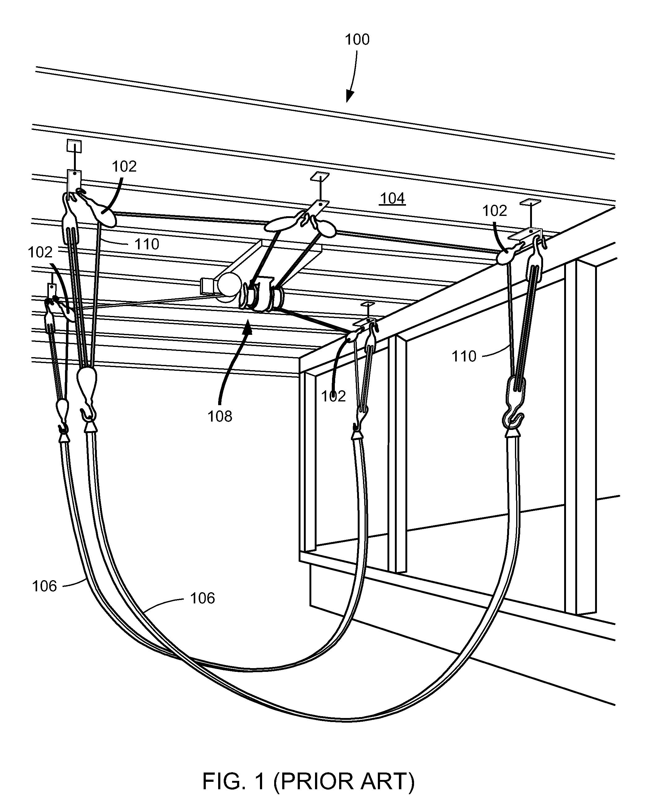
Not only are the cables unsightly, but so are the drive mechanisms; if they are not hidden in an overhead attic, they are mounted in plain view to a vertical beam structure or on a boat walkway.
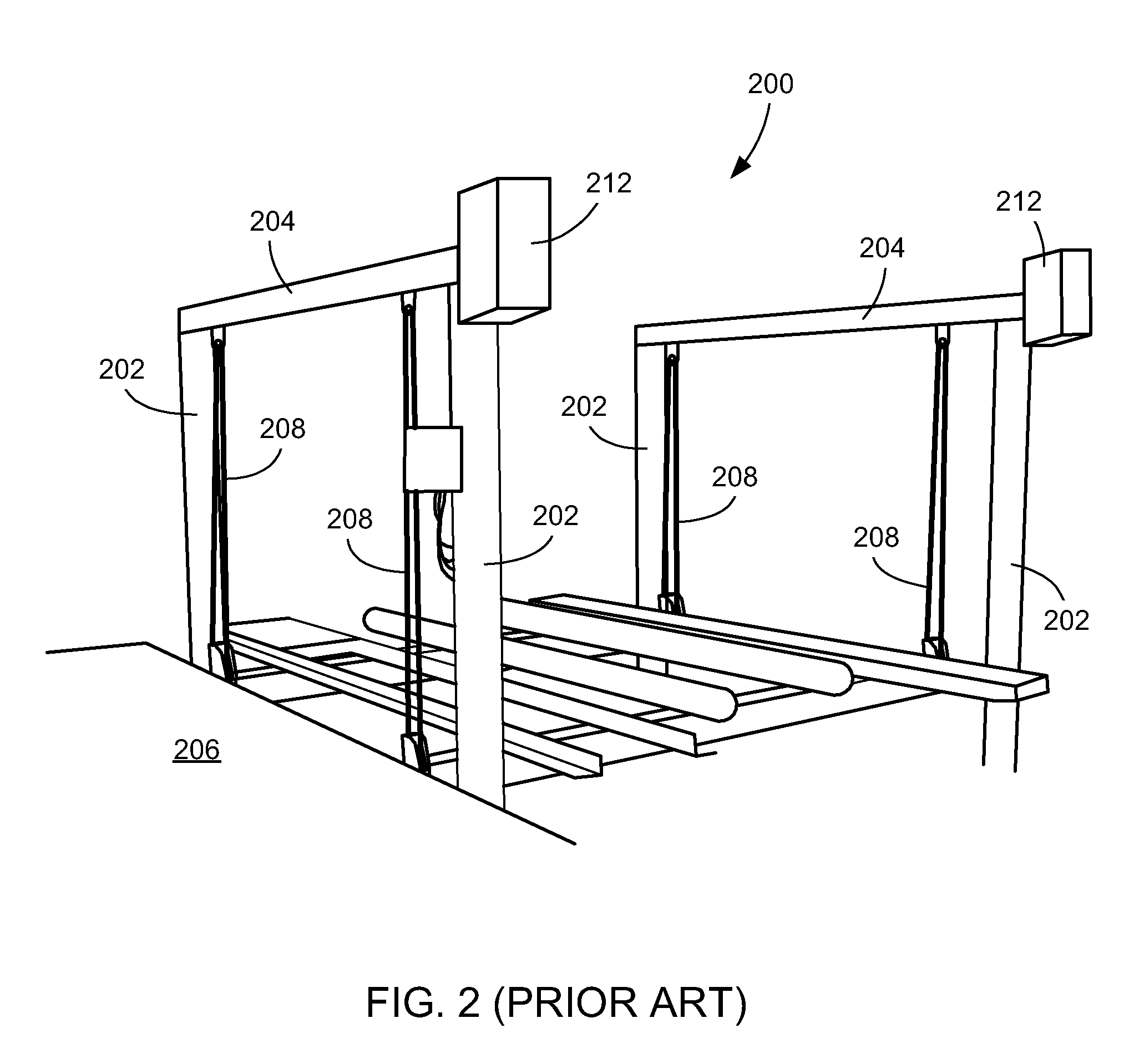
In addition, they are unstable because the cable lengths from the overhead system to the boat remain long, so that the boat tends to swing and sway in the wind particularly with the boat out of the water and in a raised position on the lift.
Further, because of their structural designs, typical boat lifts are not able to provide lifting force proportional to the balanced weight of the lifted boat and so the boat may rise unevenly.
A common complaint of these boat lifts is that the cables and drive system components are unsightly.
Another disadvantage of prior art boat lifts is that they are unstable because the lifted boats tend to swing and sway in the wind due to the long cable length remaining between fixed points on the boat lift, even with the boat in a lifted position.
Further, because of their structural designs, typical boat lifts are not able to provide lifting force proportional to the balanced weight of the lifted boat and the boat may lift unevenly.

Method used


Image

  • Boat lift
  • Boat lift
  • Boat lift

Examples


embodiment 1700

[0058]As mentioned above, many embodiments of cable drive systems are contemplated as within the scope and spirit of the present invention. Examples of the preferred embodiments of the present invention are shown in FIGS. 17A through 20. FIG. 17A shows a preferred spool-type embodiment 1700 as generally including two cogged spools 1702 with intermeshing cogs 1704 axially extending about their circumferences. The spools are preferably located within the interior of the support beam body 1706 and are rotatably affixed to the support beam 1706 so that attached cables 1708 can be wrapped around them as shown in the FIGS. Both of the cogged spools 1702 may be powered, but both cogged spools may turn if only one of the two cogged spools 1702 is powered provided that the other non-powered spool is connected to the powered spool. As shown in FIGS. 17A and 17B, the cogs 1704 are intermeshed so that the motion of one spool 1702 engenders motion of the other spool 1702. In this embodiment as i...

embodiment 1900

[0060]Another preferred embodiment is shown in FIG. 19. In this embodiment, dual opposing hydraulic assembly 1900 generally includes two hydraulic cylinder assemblies 1902. The assemblies 1902 each include a hydraulic cylinder, hydraulic rod and pulley block. As shown in FIG. 19, the assemblies 1900 are arranged opposite to each other so that the rods extend in opposite directions. This embodiment allows for greater lifting capacity of the single support beam they are mounted in, and / or increased cable withdrawal capacity because only a single cable is wrapped around each assembly 1902. The single hydraulic cable drive embodiments of previous figures typically require two cables to be wrapped around the hydraulic cylinder, rod and pulley block assembly, thereby allowing only half as many turns of cable as the embodiment 1900 of FIG. 19.

[0061]Yet another preferred embodiment is shown in FIG. 20. Dual extension hydraulic assembly 2000 generally includes two hydraulic cylinder, rod and...


PUM


Abstract

An apparatus and method are described for lifting a boat out of water. An improved boat lift having at least one support beam upon which the weight of a boat rests, the support beams having an interior wherein components of a cable drive system are mounted, provides lifting force through operation of the cable drive system, which withdraws the support cables to within the interior of the support beams, the cables attached at one of their ends to fixed points external to the beam.

Description

[0001]This application claims priority from U.S. Provisional Application 61 / 161,649, filed Mar. 19, 2009, which is hereby incorporated by reference.TECHNICAL FIELD OF THE INVENTION[0002]The present invention relates generally to vehicle lifts, and more particularly to a mechanism for lifting boats.BACKGROUND OF THE INVENTION[0003]The cleaning, repairing and storing of a boat is most effectively performed by lifting the boat out of the water. To this end, boat lifts have been valuable and widely used. However, they tend to be unsightly, unstable and functionally inefficient.[0004]A typical boat lift employs several pulleys and cables mounted overhead the boat, with the lifting mechanism (cable drive system) in an attic or upper part of an overhead dock or vertical beam structure. In these systems, cables extend from the overhead drive mechanism down to the boat support structure in the water. Not only are the cables unsightly, but so are the drive mechanisms; if they are not hidden i...

Claims


Application Information

Patent Timeline
IPC IPC(8): B63C3/06
CPCB63C3/06E02C5/00
Inventor BROWN, CURTIS
Owner BROWN CURTIS
Learn More