
Multi channel encoder, demodulator, modulator and digital transmission device for digital video insertion in network edge applications

a digital video and network edge technology, applied in the field of digital video encoding, can solve the problems of inability to scale, inherently not suitable for mdu environments, and inability to be designed in a manner, and achieve the effect of convenient scaling and easy access

Inactive Publication Date: 2010-09-23
ADC TELECOMMUNICATIONS
View PDF2 Cites 8 Cited by
  • Summary
  • Abstract
  • Description
  • Claims
  • Application Information

AI Technical Summary

Benefits of technology

[0019]It is still another object of the invention, in at least some embodiments, to provide a digital video insertion system that is easily scalable. This scalability is achieved through plug-in application cards located on an interface that is easily accessed by the user.
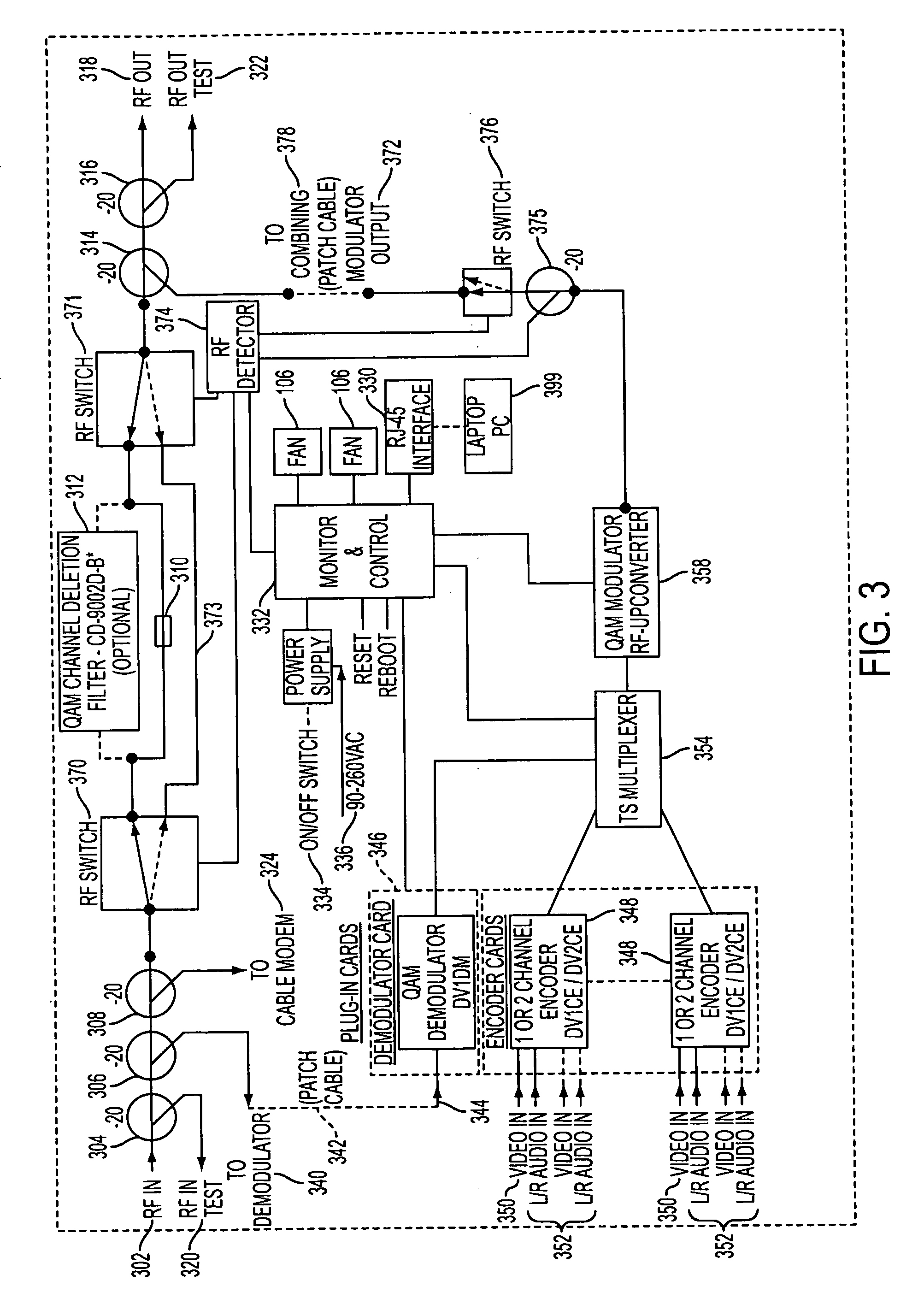
[0020]It is still another object of the invention, in at least some embodiments, to provide a DVIS having integrated RF management functionality (RF ports for input and output test points, RF tap ports for input signal to be directed to a demodulator, RF tap ports for input signal to be directed to a cable modem, RF ports for the coupling of the device's output and the incoming spectrum), the ability to house a channel deletion filter, both of which allow for an efficient and craft friendly method of installing this equipment at a location for its intended application.
[0026]To achieve the above and other objects, the present invention is directed to a DVIS designed to be installed in an MDU / commercial property environment, where a traditional rack mount product would not be easily installed. In MDU environments, a wall-mounted cabinet which integrates all the necessary technology for any of its intended applications is far more efficient for an operator. Further, since it is a cabinet that can be opened in order to access the front panel to remove and / or add plug-in application cards, it is far more efficient for an operator to scale its functionality.
[0031]At least some embodiments have been designed for use by an MSO—CATV operator. However, the base design of the invention can easily be extrapolated to satisfy a number of other applications in other markets such as Satellite (Dish) and telephone companies (like Verizon).
[0051]All of this functionality can be performed while maintaining MPEG 2 TS specifications so that the video is not compromised (e.g., PCR insertion).
[0053]front access so that input and output cards are easily slid in and out of the chassis

Problems solved by technology

However, those systems are not designed in a manner that has been optimized for an MDU or other similar application.
The EGT HEMi™ is a rack mount PC based product and inherently is not suitable for an MDU environment from both an installation and environmentally hardened standpoint.
Because the platform is PC based and therefore the application cards (e.g., Encoders and demodulators) are PCI interface based, it is not easily scaled, since it requires the removal of the cover in order to install new application cards.
This product does not contain the complete RF management functionality (RF ports for input and output test points, RF tap ports for input signal to be directed to a demodulator, RF tap ports for input signal to be directed to a cable modem, RE ports for the coupling of the device's output and the incoming spectrum), nor the ability to house a channel deletion filter.
The HEMi™ is not provided in a wall mount cabinet style housing with a lockable front door and therefore is easily tampered with.
Further, the lack of a cabinet-style housing does not provide the opportunity for a user to easily and securely co-locate a communications device (e.g., Cable modem) with the product so that it can easily be monitored and controlled from a remote location.
The HEMi™ does not provide field-removable power supply or cooling fans, making this difficult to service in the field in the event that any of these components fail.
The EGT HEMi™ is limited to a power supply that can accept power from the utility power only and does not provide a power supply that can be powered from an MSO's power supply.
The Radiant QRF products are based on 1RU rack mounted chassis instances and are therefore not MDU environment suitable.
This is cumbersome for an operator to install and manage and further increases the potential for failure of the applications, as more devices lead to a greater chance of a device failing.
The QRF series is not provided in a wall mount cabinet style housing with a lockable front door and therefore is easily tampered with.
Further, the lack of a cabinet-style housing does not provide the opportunity for a user to easily and securely co-locate a communications device (e.g., Cable modem) with the product so that it can easily be monitored and controlled from a remote location.
The QRF does not provide a field-removable power supply or cooling fans, making this difficult to service in the field in the event that any of these components fail.
The QRF is limited to a power supply that can accept power from the utility power only and does not provide a power supply that can be powered from an MSO's power supply.
The QRF does not provide an integrated RF bypass switching functionality that is used in add / drop applications in order to allow the incoming RF signal to be passed based on the loss of power in the unit or loss of the QRF's QAM output signal.
Further, the QRF does not incorporate a QAM output switch that terminates the output until the product is fully booted and the QAM output is stabilized and is ready to be transmitted out of the product.

Method used


Image

  • Multi channel encoder, demodulator, modulator and digital transmission device for digital video insertion in network edge applications
  • Multi channel encoder, demodulator, modulator and digital transmission device for digital video insertion in network edge applications
  • Multi channel encoder, demodulator, modulator and digital transmission device for digital video insertion in network edge applications

Examples


Embodiment Construction

[0086]A preferred embodiment of the present invention will be set forth in detail with reference to the drawings, in which like reference numerals refer to like elements throughout.

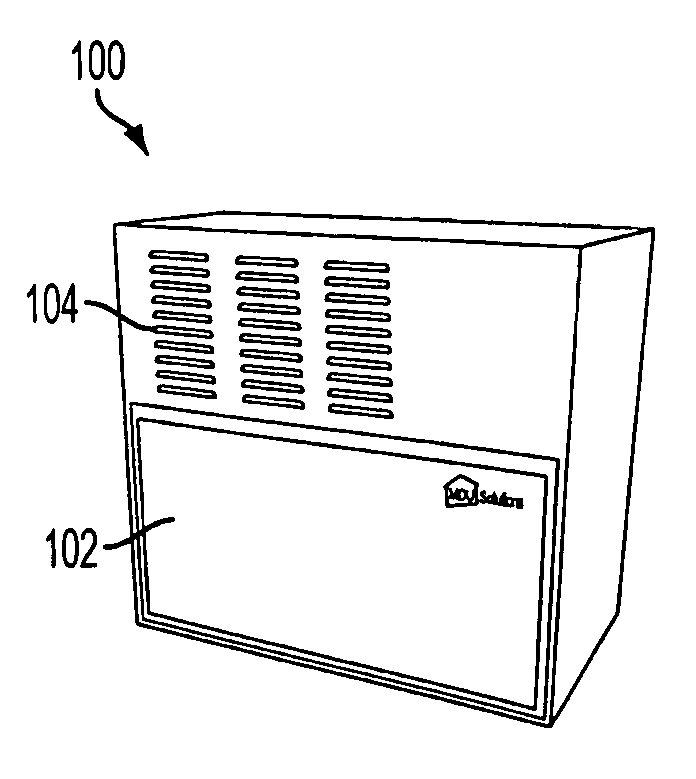
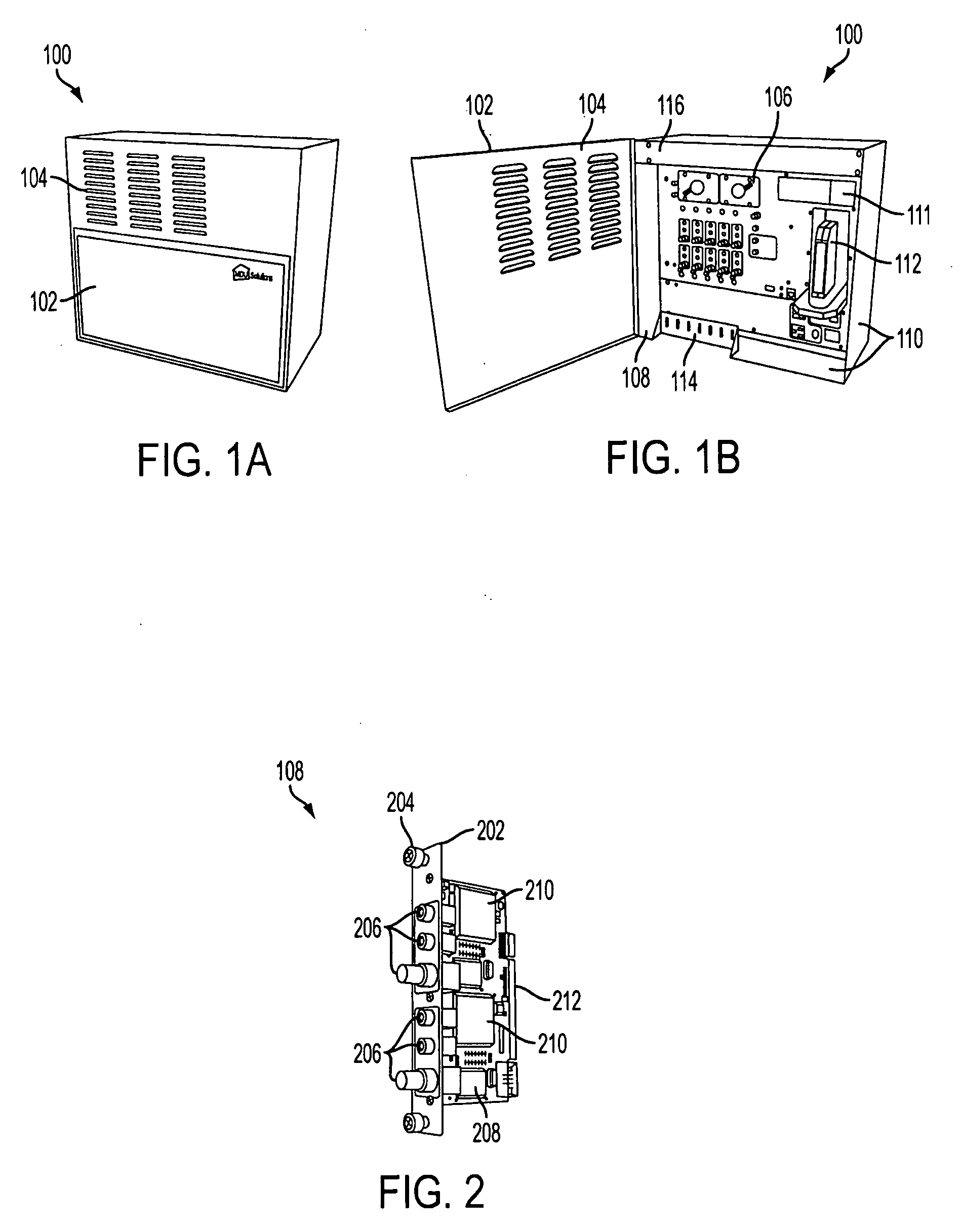
[0087]FIG. 1A shows a perspective view of the system 100 with the front door 102 closed. The front door 102 is front-mounted to allow easy access in an MDU installation and has louvers 104 to allow air circulation for cooling. The front door 102 is lockable to provide a lockable cabinet with ability to house a communications device such as a cable modem.

[0088]FIG. 1B shows the system of FIG. 1A with the door 102 open, so that components which are concealed with the door 102 closed can be seen. The system includes removable cooling fans 106 above encoder or demodulator / units where 108 is illustrative of their appearance and form factor. The encoder or demodulator units 106 are hot-swappable and accessible from the front of the unit, so that a person standing in front of the system can easily insert and rem...


PUM


Abstract

A DVIS designed to be installed in an MDU / commercial property environment has a wall-mounted cabinet which integrates all the necessary technology for any of its intended applications. The cabinet can be opened in order to access the front panel to remove and / or add plug-in application cards. A channel deletion filter can be used to produce an empty QAM slot into which locally produced programming can be inserted. The invention is applicable to digital video encoding (e.g., MPEG-2 or MPEG-4), reception and demodulation, multiplexing and digital transmission (e.g., QAM modulation / transmission) and more specifically to a multiple-channel encoder suitable for use in a location at the edge of a broadband network. Depending on the terminology, the edge of the network can range from the last centralized point of a broadband service provider's architecture (e.g., Hub site for MSO) or even the to the subscriber premise itself.

Description

FIELD OF THE INVENTION[0001]The present invention is directed to a digital video encoding (e.g., MPEG-2 or MPEG-4), reception and demodulation, multiplexing and digital transmission (e.g., QAM modulation / transmission) and more specifically to a multiple-channel encoder suitable for use in a location at the edge of a broadband network. Depending on the terminology, the edge of the network can range from the last centralized point of a broadband service provider's architecture (e.g., Hub site for MSO) or even the to the subscriber premise itself.DESCRIPTION OF RELATED ART[0002]Digital video insertion systems are known in the art. Such systems allow broadband operators (e.g., MSOs, Telcos, Satellite) to insert content (audio, video and data) that is locally generated at locations at the edge of the network in a digital format. Typically these locations are referred to as MDUs (Multi Dwelling Units) and / or commercial properties. Digital video insertion systems can also be used for close...

Claims


Application Information

Patent Timeline
IPC IPC(8): H04N11/02H04N11/04
CPCH04N7/102
Inventor VELJKOVIC, SASAMARTIN, RICHARDLEE, JAY
Owner ADC TELECOMMUNICATIONS
Learn More