
Transparent Organic Light Emitting Diode Lighting Device

a light emitting diode and organic technology, applied in the direction of organic semiconductor devices, solid-state devices, greenhouse gas reduction, etc., can solve the problems of not being able to recognize the opposite object under the bidirectional lighting from the light of the lighting device, and cannot be used as window-type lighting devices

Inactive Publication Date: 2010-09-23
ELECTRONICS & TELECOMM RES INST
View PDF3 Cites 84 Cited by
  • Summary
  • Abstract
  • Description
  • Claims
  • Application Information

AI Technical Summary

Problems solved by technology

Here, the top or bottom emission type OLED lighting devices are not transparent, and thus cannot be used as window type lighting devices.
However, in the case of the transparent OLED lighting devices in which bidirectional lighting is possible, a user cannot control a light emitting direction when intending to send light only in one direction according to a purpose.
Further, when intending to recognize an object opposite the lighting device, the user cannot recognize the opposite object under the bidirectional lighting from light of the lighting device.
However, these double-sided light emitting devices can control only color and quantity of the emitted light, but not a direction of the emitted light.

Method used


Image

  • Transparent Organic Light Emitting Diode Lighting Device
  • Transparent Organic Light Emitting Diode Lighting Device
  • Transparent Organic Light Emitting Diode Lighting Device

Examples


Embodiment Construction

[0023]The present invention will be described more fully hereinafter with reference to the accompanying drawings, in which exemplary embodiments of the invention are shown. This invention may, however, be embodied in different forms and should not be construed as limited to the embodiments set forth herein. In the following description of the present invention, a detailed description of known functions and components incorporated herein will be omitted when it may make the subject matter of the present invention rather unclear. It should be noted that the same reference numbers are used in the figures to denote the same elements.

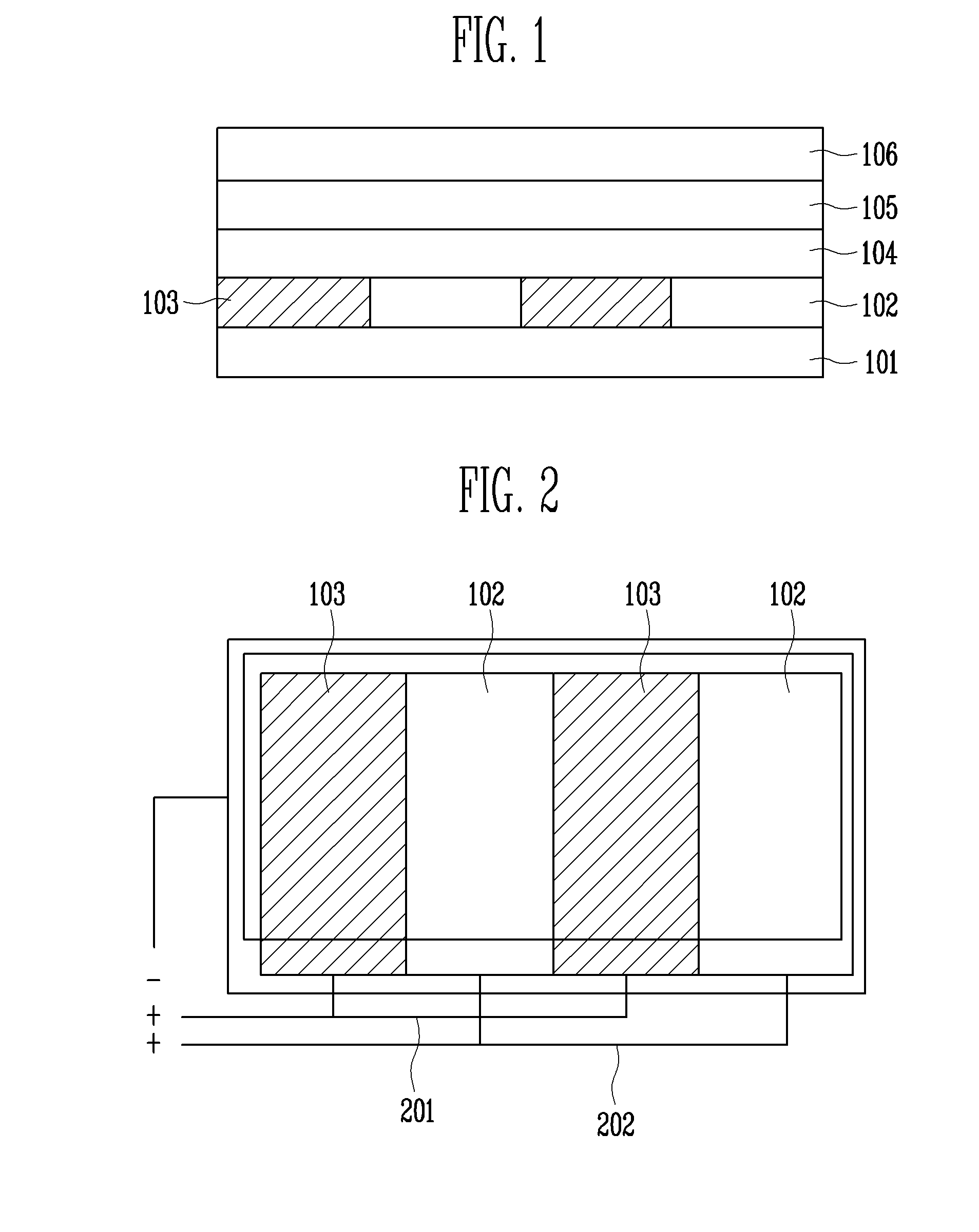
[0024]FIG. 1 is a cross-sectional view of a transparent OLED lighting device according to a first exemplary embodiment of the present invention.

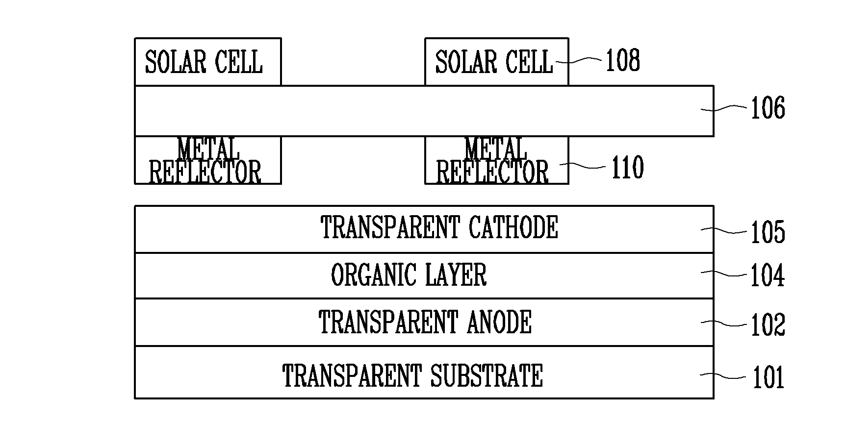
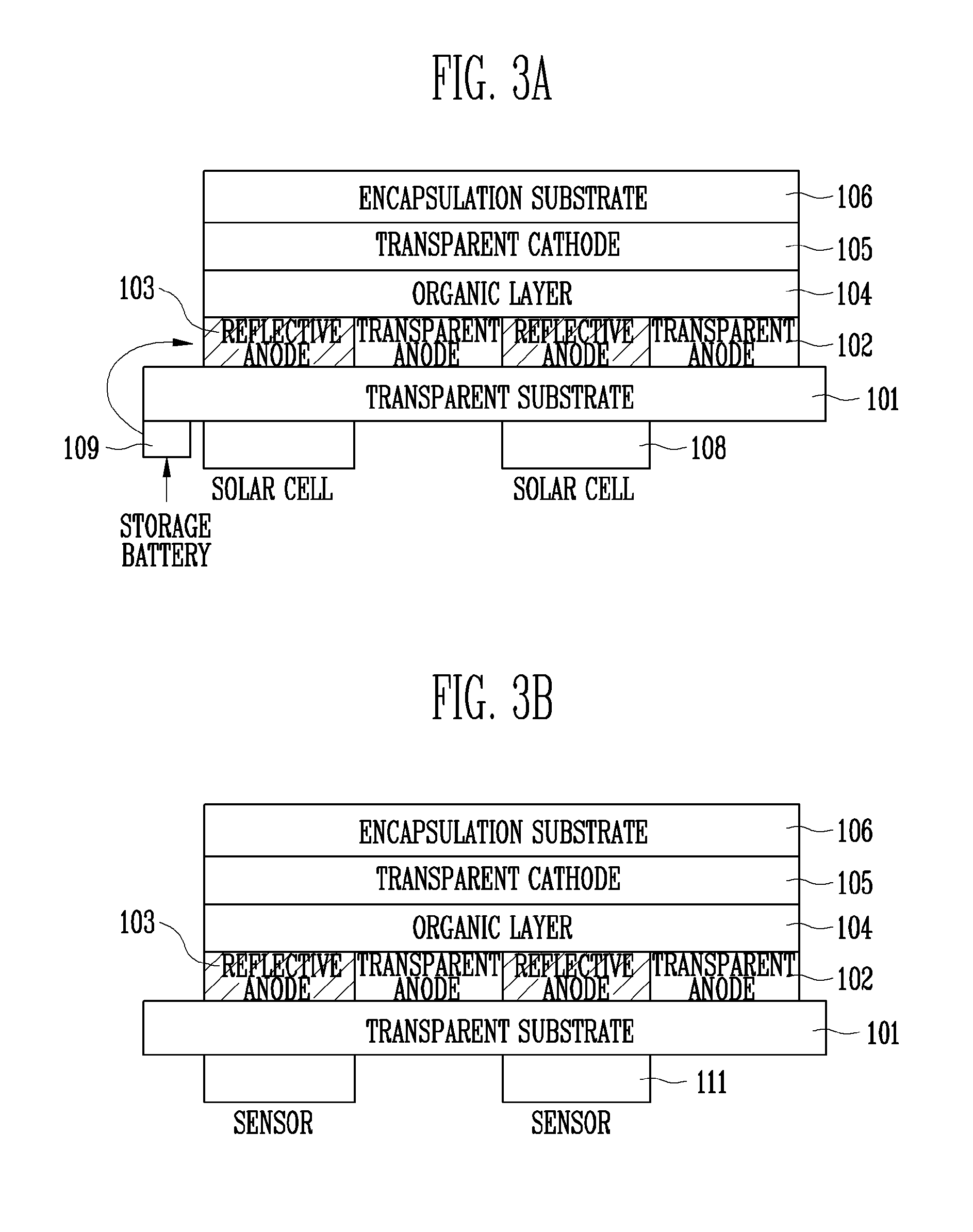
[0025]Referring to FIG. 1, a transparent OLED lighting device according to the first exemplary embodiment of the present invention includes a transparent substrate 101, a transparent anode 102 formed on a predetermin...


PUM


Abstract

Provided is a transparent organic light emitting diode (OLED) lighting device in which opaque metal reflectors are formed to adjust light emitting directions. The transparent OLED lighting device includes a transparent substrate, a transparent anode formed on a predetermined region of the transparent substrate, a reflective anode formed adjacent to the transparent anode on another region of the transparent substrate, an organic layer formed on the transparent and reflective anodes, and a transparent cathode and an encapsulation substrate sequentially stacked on the organic layer. Directions of light emitted from the organic layer vary depending on the current applied to the transparent and reflective anodes.

Description

CROSS-REFERENCE TO RELATED APPLICATION[0001]This application claims priority to and the benefit of Korean Patent Application Nos. 10-2009-0023932 filed Mar. 20, 2009, and 10-2010-0023167 filed Mar. 16, 2010, the disclosure of which is incorporated herein by reference in its entirety.BACKGROUND[0002]1. Field of the Invention[0003]The present invention relates to a transparent organic light emitting diode (OLED) lighting device and, more particularly, to a transparent OLED lighting device in which opaque metal reflectors are formed to control light emitting directions.[0004]2. Discussion of Related Art[0005]Recently, the display industry has been developed in response to demands for small size, light weight, and thin thickness using thin films, as well as high resolution. According to this demand, research on display devices that embody the small size, light weight, and thin thickness using a plastic or metal thin film as a substrate instead of liquid crystal display (LCD) devices usi...

Claims


Application Information

Patent Timeline
IPC IPC(8): H01L51/52
CPCH01L27/288H01L27/3227H01L51/5206H01L51/5271H01L31/056H01L2251/5323H01L2251/5361Y02E10/52H02S40/38H01L2251/5315Y02E70/30H10K65/00H10K59/60H10K50/818H10K50/856H10K2102/3031H10K2102/3026H10K50/81
Inventor CHU, HYE YONGLEE, JEONG IKLEE, JONG HEECHO, KYOUNG IK
Owner ELECTRONICS & TELECOMM RES INST
Learn More