Multi-stage centrifugal pump (axial face seal)

Active Publication Date: 2010-09-16
GRUNDFOS MANAGEMENT AS
View PDF3 Cites 1 Cited by
  • Summary
  • Abstract
  • Description
  • Claims
  • Application Information

AI Technical Summary

Benefits of technology

[0008]This solution according to the present invention utilizes the otherwise unused transition region of the shaft, thus the diameter difference between the groove base of the splined shaft section towards the cylindrical section, for the arrangement of the 
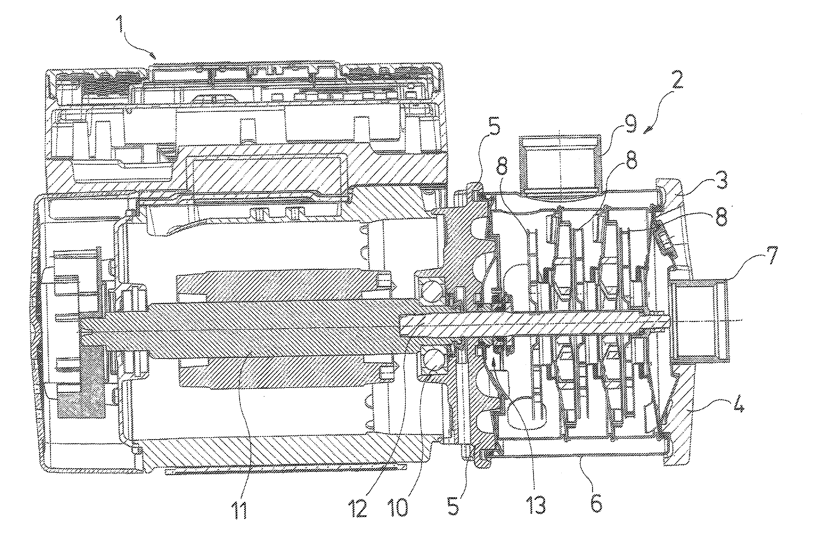
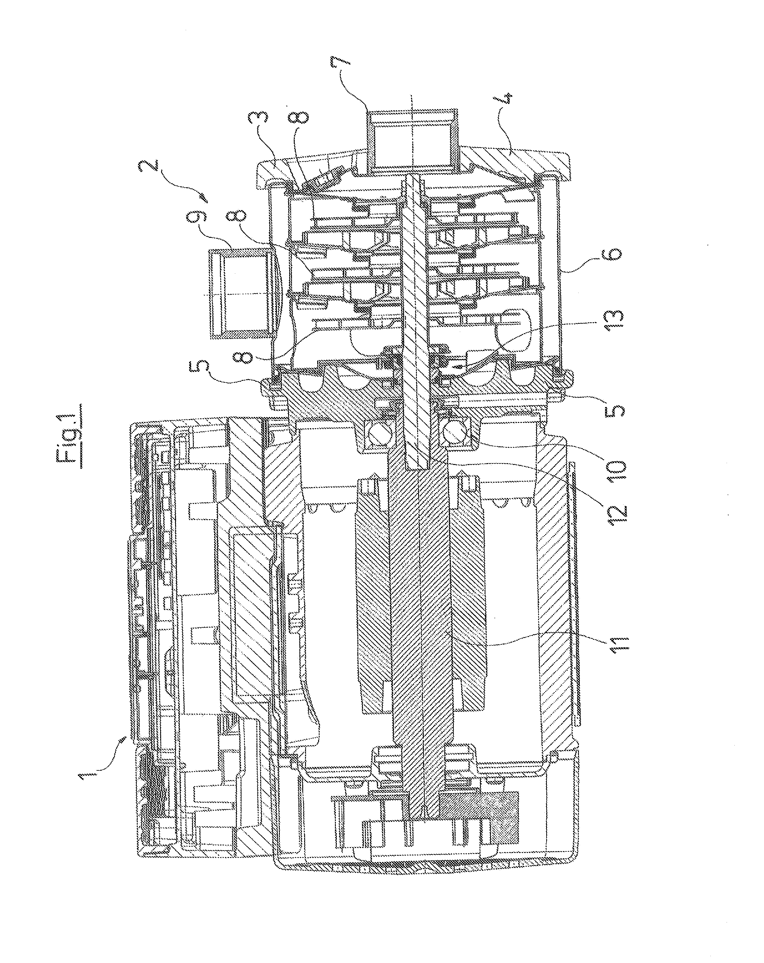
abutment ring. The abutment ring at the same time lies between the spring holders, thus in a space which otherwise is usually not used with regard to design. The axial constructional length of the pump may be considerably reduced by way of this. According to the present invention, positive-fit means are provided between the spring holders and transmit the rotational movement of the shaft from the splined shaft section onto the pump-side spring holder, and, via the positive-fit means, onto the motor-side spring holder and from there onto the rotating axial face seal ring, in order to let the axial face seal ring rotating together with the shaft co-rotate, without loading its sealing with respect to the shaft.
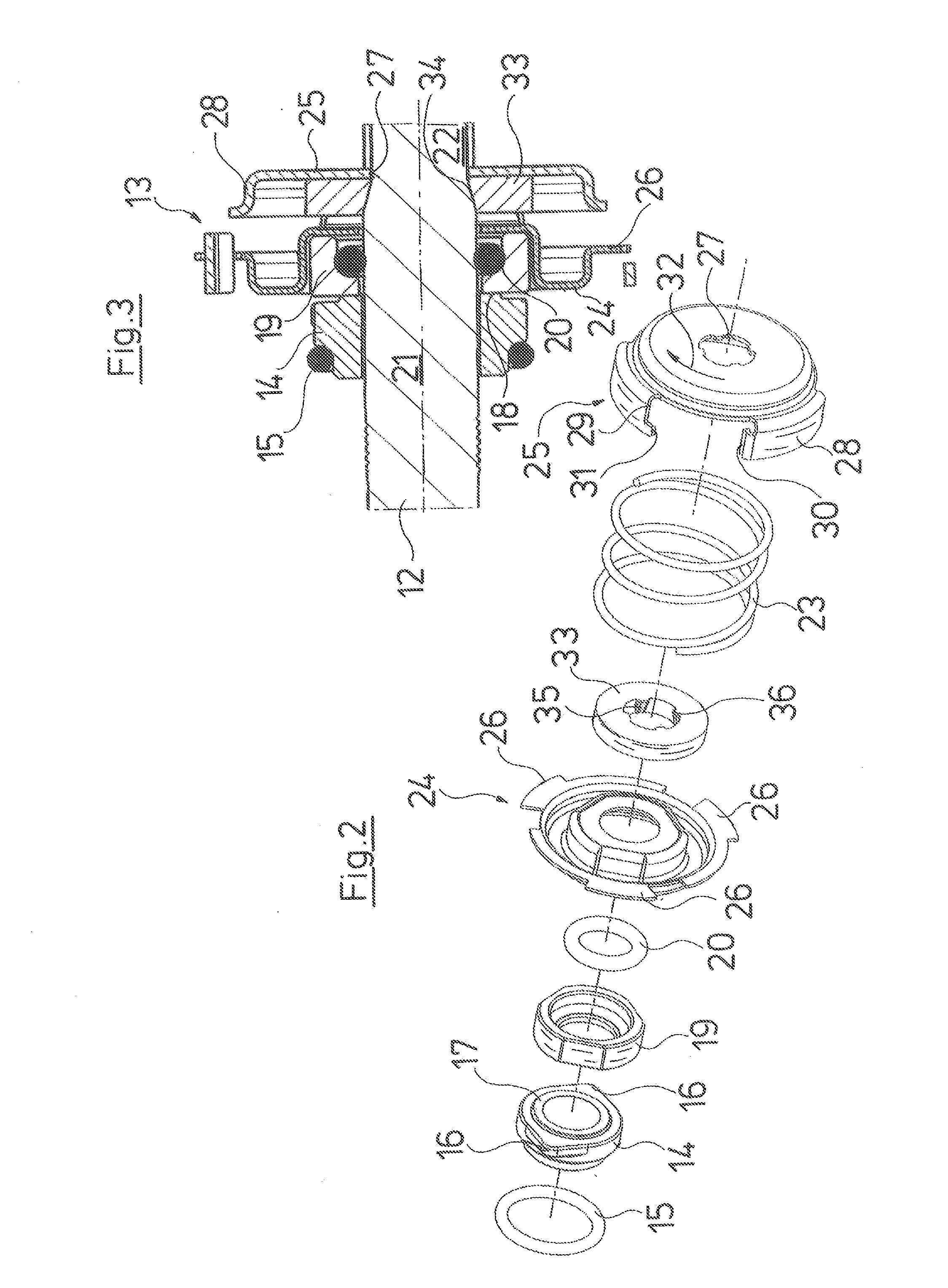
[0012]Simultaneously, the abutment ring may correspond roughly to the inner diameter of the spring, and by way of this, may accommodate the forces of the oblique surface of the transition region without deforming. This may be effected advantageously by way of the provision of a helical compression spring as spring means. Such helical compression springs ensure an adequate spring path with a suitable design, are inexpensive in manufacture and, with a suitable dimensioning, are sufficient in mustering the required forces.
[0013]The design according to the present invention is preferably such that the axial face seal is not assembled from the motor side, but from the pump side of the shaft. In order then to simplify the assembly and in particular to ensure that the abutment ring remains in its correct position, according to a further formation of the present invention, a positive fit means may be provided on the spring holders, with which these may be fixed axially to one another at least in one direction under the biasing of the spring means, for the purpose of assembly. Thus the spring means during the assembly are biased by way of these positive fit means of the spring holders, and the spring means are practically deactivated with regard to their action. Only when the assembly is completed and the last pump impeller is applied onto the shaft and clamped, are these positive fit means released, in order to muster the necessary axial pressure on the axial face seal, in particular on the rotating axial face seal ring. For this, according to the present invention, one may provide a type of bayonet connection between the spring holders. It is particularly advantageous if the bayonet connection is designed such that the locking is effected opposite to the working direction or that the locking is automatically lifted on moving the shaft in the working rotation direction. Such an arrangement has the advantage that no separate working step is necessary for releasing the positive-fit means between the spring holders, but that these are released automatically on starting up the centrifugal pump in the working rotation direction.
[0018]In order to prevent a wear of the bearing surface occurring in the recess, in particular when the previously mentioned parts are formed of sheet metal, according to a further formation of the present invention, the edges of the recesses are designed reinforced in the engagement region of the projections. Such a reinforcement may be particularly simply effected by way of increasing the bearing surface, which, with a sheet metal component, may be effected for example by way of a section being bent up, so that it is not the sheet metal edge, but the flat side which forms the bearing surface. In this manner a “digging” of a projection into the bearing surface is effectively prevented.

Problems solved by technology

However, the arrangement described above necessitates a relatively large axial constructional length.

Method used


Image

  • Multi-stage centrifugal pump (axial face seal)
  • Multi-stage centrifugal pump (axial face seal)
  • Multi-stage centrifugal pump (axial face seal)

Examples


Embodiment Construction

[0024]Certain terminology is used in the following description for convenience only and is not limiting. The words “inner” and “outer” refer to directions toward and away from, respectively, the geometric center of the pump, and designated parts thereof, in accordance with the present invention. Unless specifically set forth herein, the terms “a,”“an” and “the” are not limited to one element, but instead should be read as meaning “at least one.” The terminology includes the above-listed words, derivatives thereof and words of similar import.

[0025]Referring to the drawings in detail, wherein like numerals indicate like elements throughout the several views, FIGS. 1-3 show a centrifugal pump assembly, generally designated 2, in accordance with a preferred embodiment of the present invention. The centrifugal pump assembly 2, which is represented by way of FIG. 1 in a longitudinal section, preferably includes an electric drive motor 1, on which the preferably three-stage centrifugal pum...


PUM


Abstract

An axial face seal (13), which seals a pump housing in the region of the pump shaft (12), is constructed in an axially compact manner. Spring holders (24, 25), which transmit the required pressing force of a compression spring (23), are connected to one another with a positive fit in a rotation direction, and hold a rotating axial face seal ring (19) in a rotationally fixed manner to the pump shaft (12). The spring holders (24, 25) are compact and enclose an abutment ring (33) for pump impellers as well as the compression spring (23). A motor-side spring (24) engages over the rotating axial face seal ring (19), by which an axially extremely short constructional length is achieved.

Description

BACKGROUND OF THE INVENTION[0001]The present invention relates to a multi-stage centrifugal pump.[0002]Single-stage or multi-stage centrifugal pumps are considered as belonging to the state of the art. In one aspect, the present invention relates to a multi-stage centrifugal pump whose drive shaft is arranged in a lying manner, i.e. arranged horizontally with normal operation. Such centrifugal pumps, as are considered as belonging to the state of the art, are, for example, offered by the company Grundfos in the series CH and CHN. These pumps have a pump housing with a shaft which is rotatably mounted therein and which, at its motor-side end, comprises at least one cylindrical section and connecting to this on the pump side, comprises a splined shaft section, on which impellers are arranged in a rotationally fixed manner. The impellers are clamped between an abutment ring seated on the shaft and the free shaft end. Such pumps are driven by an electric motor, whose drive shaft is conn...

Claims


Application Information

Patent Timeline
IPC IPC(8): F04D29/10F04D1/06
CPCF04D29/126
Inventor BRUHN, AAGEOSTERGAARD, LARS
Owner GRUNDFOS MANAGEMENT AS
Why Eureka
Try Eureka