
Device and method for generating a multi-channel signal including speech signal processing

Active Publication Date: 2010-09-16
FRAUNHOFER GESELLSCHAFT ZUR FOERDERUNG DER ANGEWANDTEN FORSCHUNG EV
View PDF12 Cites 41 Cited by
  • Summary
  • Abstract
  • Description
  • Claims
  • Application Information

AI Technical Summary

Benefits of technology

[0033]This prevents reproduction of speech components to take place in the back channels or ambience signal channels, which would otherwise disturb or even confuse the listener. Consequently, the invention ensures dialogs and other speech understandable by a listener, i.e. which is of a spectral characteristic typical of speech, to be placed in front of the listener.

Problems solved by technology

Nevertheless, there is a huge amount of audio material, which users own or is generally available, which only exists as stereo material, i.e. only includes two channels, namely the left channel and the right channel.
However, this solution is of disadvantage in that the plurality of loudspeakers already there is not made use of, which means that the center loudspeaker and the two back loudspeakers present are not made use of advantageously.
Upmixing errors of this kind may be particularly disturbing when signals for the back loudspeakers, which are also known as ambience signals, cannot be generated in an error-free manner.
If a special amount of speech components was to be reproduced by the back channels, this would result in the position of the speaker or of the few speakers to be placed from the front to the back or in a certain distance to the user or even behind the user, which results in a very disturbing sound experience.
In particular, in a case in which audio and video material are presented at the same time, such as, for example, in a movie theater, such an experience is particularly disturbing.
This would result in a very disturbing sound experience, in particular when the audio signals are presented simultaneously with visual signals, as is, for example, the case in movies.
Thus, many multi-channel movie sound tracks hardly contain any speech components in the back channels.

Method used


Image

  • Device and method for generating a multi-channel signal including speech signal processing
  • Device and method for generating a multi-channel signal including speech signal processing
  • Device and method for generating a multi-channel signal including speech signal processing

Examples


Embodiment Construction

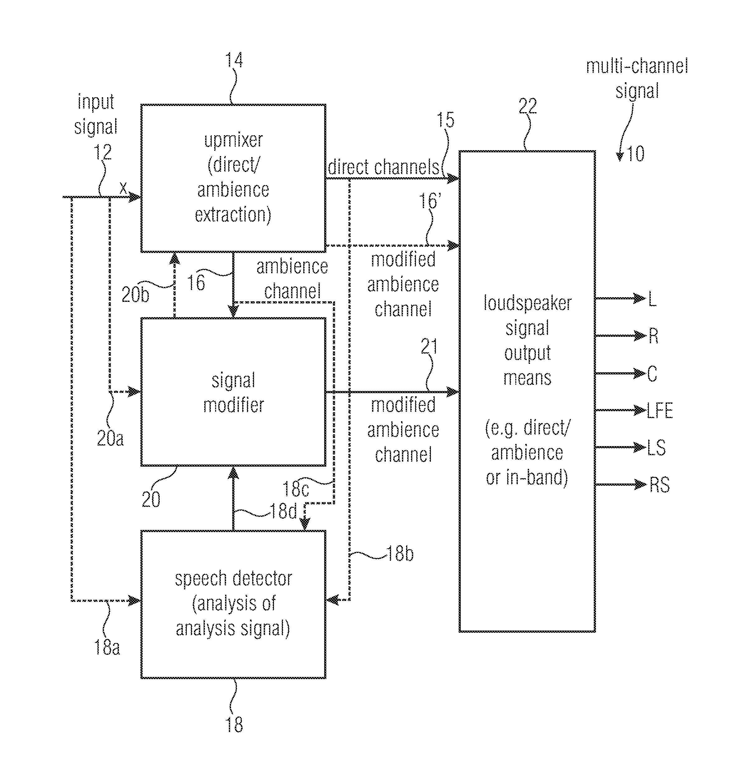
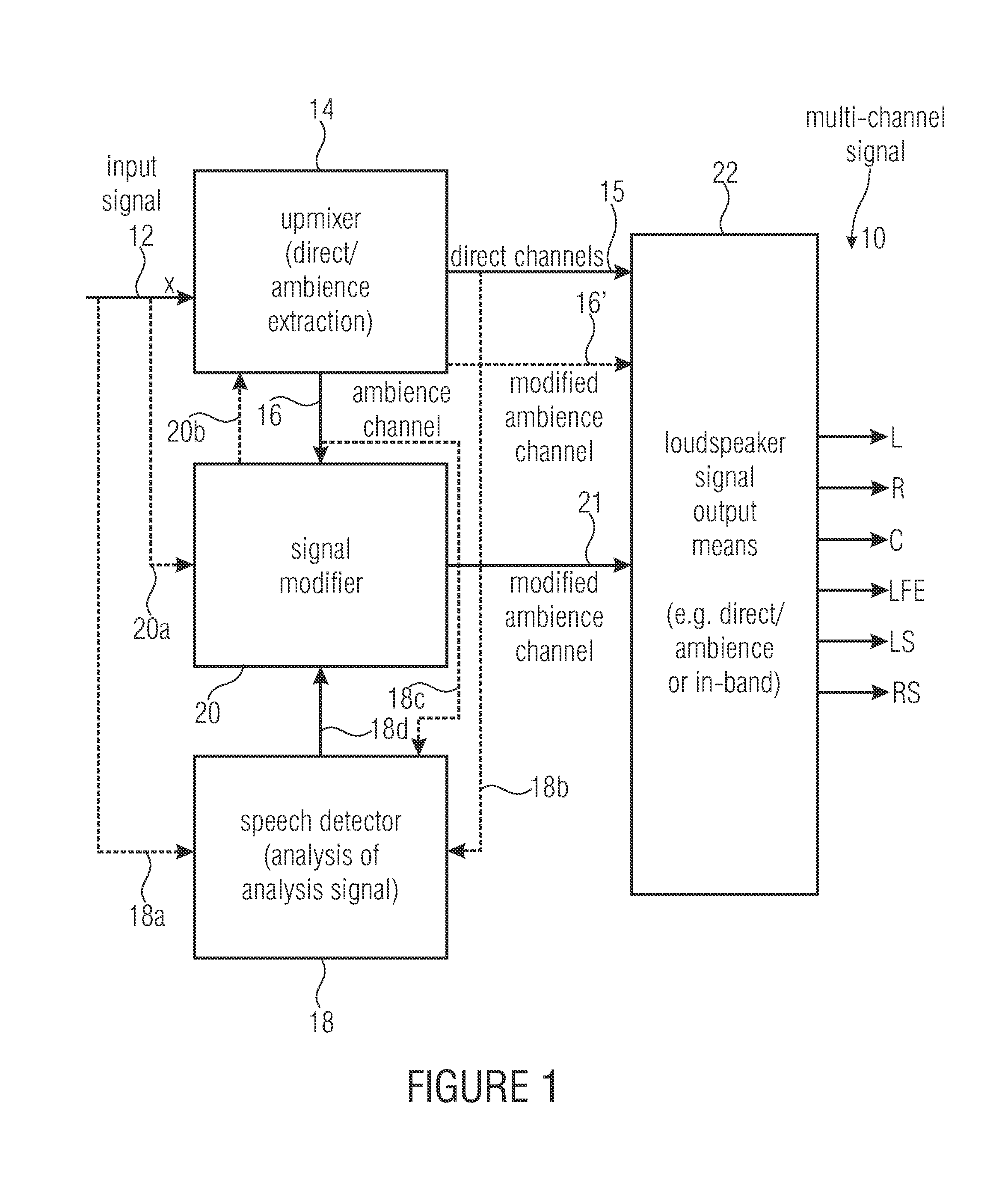
[0052]FIG. 1 shows a block diagram of a device for generating a multi-channel signal 10, which is shown in FIG. 1 as comprising a left channel L, a right channel R, a center channel C, an LFE channel, a back left channel LS and a back right channel RS. It is pointed out that the present invention, however, is also appropriate for any representations other than the 5.1 representation selected here, such as, for example, a 7.1 representation or even 3.0 representation, wherein only a left channel, a right channel and a center channel are generated here. The multi-channel signal 10 which exemplarily comprises six channels shown in FIG. 1 is generated from an input signal 12 or “x” comprising a number of input channels, the number of input channels equaling 1 or being greater than 1 and exemplarily equaling 2 when a stereo downmix is input. Generally, however, the number of output channels is greater than the number of input channels.

[0053]The device shown in FIG. 1 includes an upmixer ...


PUM


Abstract

In order to generate a multi-channel signal having a number of output channels greater than a number of input channels, a mixer is used for upmixing the input signal to form at least a direct channel signal and at least an ambience channel signal. A speech detector is provided for detecting a section of the input signal, the direct channel signal or the ambience channel signal in which speech portions occur. Based on this detection, a signal modifier modifies the input signal or the ambience channel signal in order to attenuate speech portions in the ambience channel signal, whereas such speech portions in the direct channel signal are attenuated to a lesser extent or not at all. A loudspeaker signal outputter then maps the direct channel signals and the ambience channel signals to loudspeaker signals which are associated to a defined reproduction scheme, such as, for example, a 5.1 scheme.

Description

BACKGROUND OF THE INVENTION[0001]The present invention relates to the field of audio signal processing and, in particular, to generating several output channels out of fewer input channels, such as, for example, one (mono) channel or two (stereo) input channels.[0002]Multi-channel audio material is becoming more and more popular. This has resulted in many end users meanwhile being in possession of multi-channel reproduction systems. This can mainly be attributed to the fact that DVDs are becoming increasingly popular and that consequently many users of DVDs meanwhile are in possession of 5.1 multi-channel equipment. Reproduction systems of this kind generally consist of three loudspeakers L (left), C (center) and R (right) which are typically arranged in front of the user, and two loudspeakers Ls and Rs which are arranged behind the user, and typically one LFE-channel which is also referred to as low-frequency effect channel or subwoofer. Such a channel scenario is indicated in FIGS...

Claims


Application Information

Patent Timeline
IPC IPC(8): H04B3/00G10L19/00G10L19/008G10L21/02G10L25/78
CPCG10L19/008G10L21/0364H04S5/005G10L25/78
Inventor UHLE, CHRISTIANHELLMUTH, OLIVERHERRE, JUERGENPOPP, HARALDKASTNER, THORSTEN
Owner FRAUNHOFER GESELLSCHAFT ZUR FOERDERUNG DER ANGEWANDTEN FORSCHUNG EV
Learn More