
X-ray ct apparatus

Inactive Publication Date: 2010-09-16
HITACHI LTD
View PDF2 Cites 8 Cited by
  • Summary
  • Abstract
  • Description
  • Claims
  • Application Information

AI Technical Summary

Benefits of technology

[0039]As mentioned above, in accordance with the present invention, it is possible to perform multi-energy scanning which is inexpensive and has sufficient difference in X-ray effective energies compared to the multi-radiation source / multilayered-detector method or multi-layer detector method since a plurality of different tube voltages can be switched without interruption using a pair of an X-ray tube and a detector, to provide an X-ray CT apparatus comprising a multi-energy scanning function capable of acquiring high quality images with reduced image noise or streak artifacts which has a greater matter distinguishing ability than the half scan method since the scan in the respective tube voltages are full scan.BRIEF DESCRIPTION OF THE DIAGRAMS
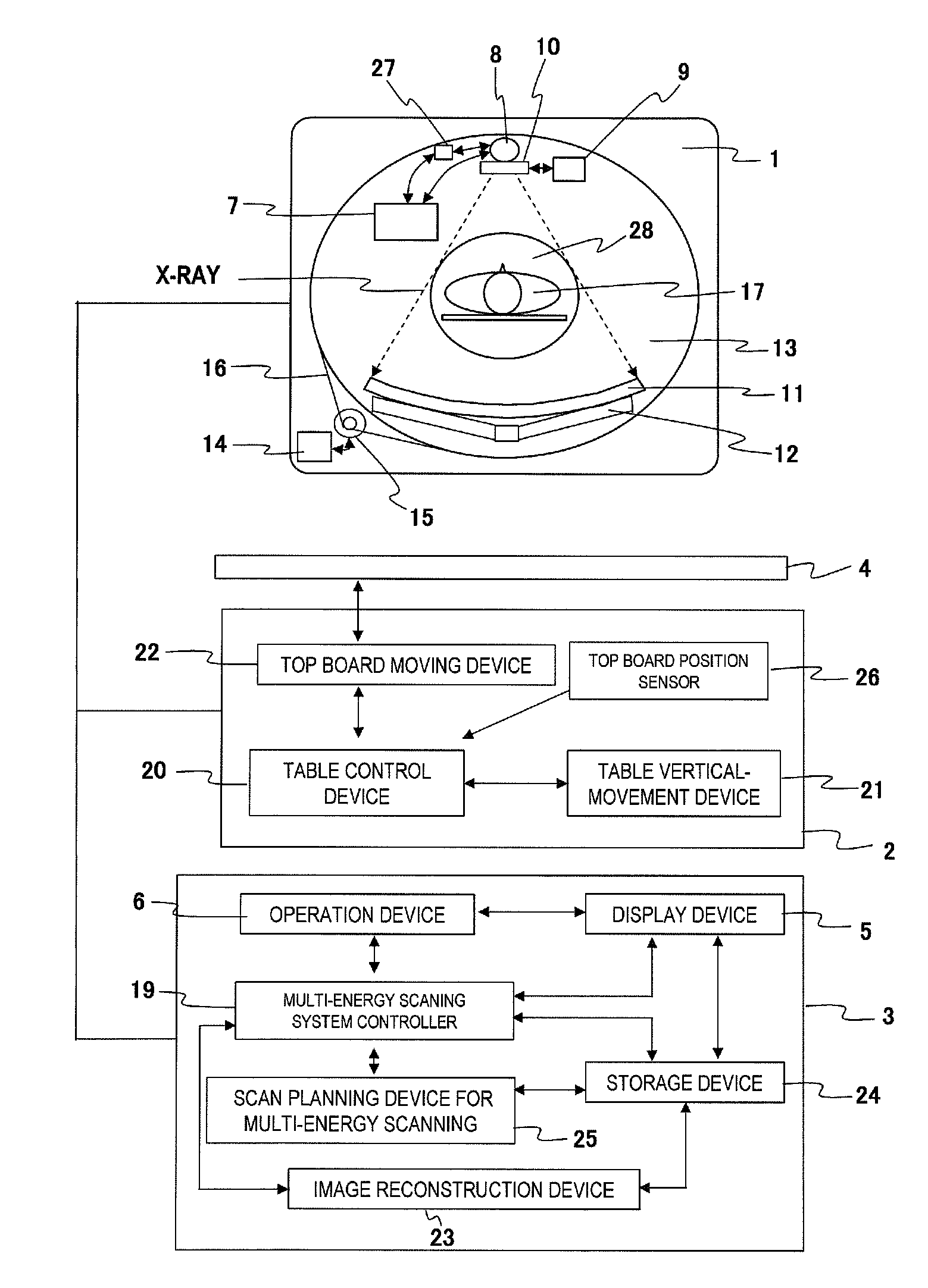
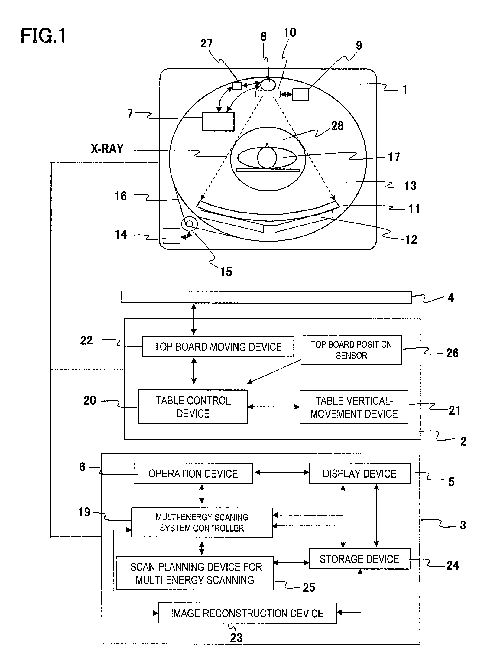
[0040]FIG. 1 is a general block diagram of the X-ray CT apparatus to which the present invention is applied.
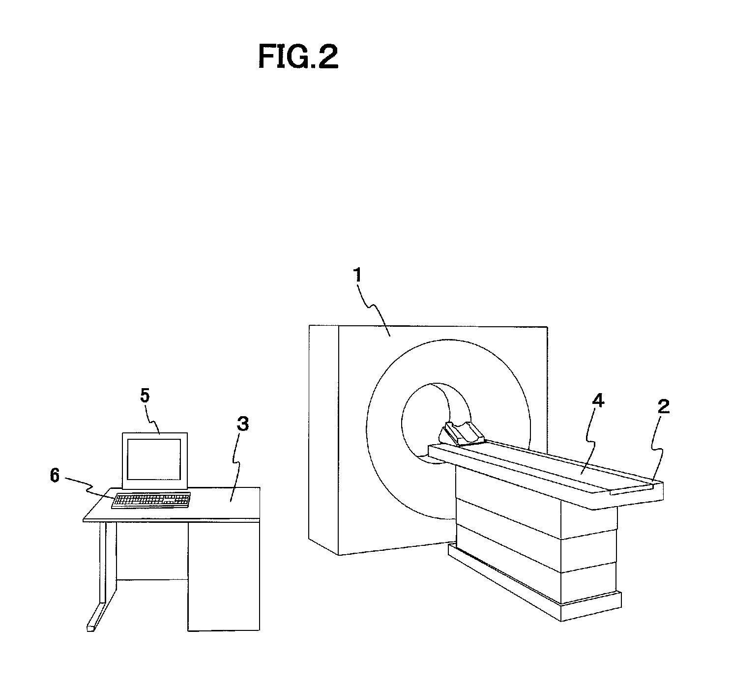
[0041]FIG. 2 is a general overview of the X-ray CT apparatus to which the present invention is applied.
[0042]FIG. 3 shows the relation between the configuration of the X-ray detector in the X-ray CT apparatus to which the present invention is applied and X-ray irradiation.
[0043]FIG. 4 is a side view showing the relationships among a scanner gantry, a table and an object of the X-ray CT apparatus to which the present invention is applied.
[0044]FIG. 5 is an operation flowchart for multi-energy scanning using multi-energy full scan related to the present invention.

Problems solved by technology

However, the above-described multi-energy scanning methods have the problems below in economical efficiency and performance.
Since a plurality of X-ray sources and X-ray detectors need to be mounted in a scanner rotation unit, the apparatus becomes large in size and expensive.

Method used


Image

  • X-ray ct apparatus
  • X-ray ct apparatus
  • X-ray ct apparatus

Examples


first embodiment

[0050 of the X-ray CT apparatus related to the present invention will be described below in detail referring to the attached diagrams.

[0051]While the present invention is applicable to any of the single-slice type and multi-slice type, the case that is applied to the multi-slice type X-ray CT apparatus will be described here.

[0052]FIG. 2 shows a general overview of the X-ray CT apparatus to which the present invention is applied, and FIG. 1 shows the general configuration thereof.

[0053]The X-CT apparatus shown in FIG. 2 irradiates X-rays to an object to be examined and collects data of the X-rays transmitted through the object so as to acquire tomographic images of the collected X-ray data by performing reconstruction calculation. It is configured by scanner gantry 1 configured to irradiate X-rays to the object and collects the X-ray data transmitted through the object, table 2 comprising movable top board 4 on which the object is to be placed, and console 3 comprising operation dev...

second embodiment

[0141 of the present invention will be described below. The difference from the first embodiment is that while the CT scanning using the first X-ray energy and the CT scanning using the second X-ray energy are executed by one rotation scan (full scan) in the first embodiment, they are to be executed in the second embodiment continuously by half scan which is less than one rotation and preferably with scan angle of (½ rotation+fan angle of X-ray beam≈240°.

[0142]In order to execute the above-mentioned process, the following changes need to be made in the previously described first embodiment:

(a) Change the scan angle of 1 scan to α (<360°, or the measurement view number of 1 scan to the one to correspond to half-scan. Corresponding to this change, for example, change the position of an angle detecting sensor for 1 scan or the maximum value of the counter of measurement view per one scan.

(b) Change the scanning start phase. Corresponding to this change, for example, when the scanning s...


PUM


Abstract

Provided is an X-ray CT apparatus which can perform CT scan of multi-energy scanning at a high speed and can obtain an image having an excellent substance distinguishing ability.The X-ray CT apparatus includes: means to continuously perform a first CT scanning using a first X-ray energy and a second CT scanning using a second X-ray energy without interrupting CT scan; means to transit the X-ray energy emitted from the X-ray during a transition period TR including an end of the first CT scanning and a beginning of the second CT scanning from the first X-ray energy to the second X-ray energy; and means to compensate the scan data in the transition period by the opposing data in the residual scan period so as to reconstruct an image.

Description

TECHNICAL FIELD[0001]The present invention is related to an X-ray CT apparatus, particularly to the X-ray CT apparatus provided with a multi-energy scanning function.BACKGROUND ART[0002]In recent years, the X-ray CT apparatus provided with multi-energy scanning function has been developed capable of acquiring CT images by different effective photon energies by using a plurality of different tube voltages upon scanning the same tomographic plane or providing discriminating function of X-ray photon energies to an X-ray detector.[0003]The advantage of the multi-energy scanning is that it is possible to distinguish the subjects, for example a bone and a contrast-filled blood vessel having proper concentration that are difficult to distinguish by a single effective energy since the CT values of the subjects are the same, by using different effective energies which makes the subjects have different CT values.[0004]The configuration methods for the X-ray CT apparatus comprising the above-m...

Claims


Application Information

Patent Timeline
IPC IPC(8): A61B6/03
CPCA61B6/032A61B6/405A61B6/545A61B6/488A61B6/482
Inventor HIROKAWA, KOICHIGOTO, TAIGAKADOMURA, TAKAYUKI
Owner HITACHI LTD
Learn More