
Wireless temperature sensor network

a temperature sensor and wireless technology, applied in the field of wireless networks, can solve the problems of multi-path problems, unsuitable for space platforms, known types of passive transponders, etc., and achieve the effect of sufficient operating power and reliably responding to the query signal

Active Publication Date: 2010-09-16
RAYTHEON CO
View PDF5 Cites 55 Cited by
  • Summary
  • Abstract
  • Description
  • Claims
  • Application Information

AI Technical Summary

Benefits of technology

The present invention provides a wireless sensor network that is suitable for use in space vehicles. The network consists of a base station and a plurality of transponder units. The base station generates a query signal with an identification code and sends it to the transponder units. The transponder units receive the query signal, generate a reply signal with the identification code, and return it to the base station. The base station and transponder units communicate using a dual carrier manner with split querying and replying frequencies. The transponder units are passive and recover operating power from the query signal. They include an analog temperature sensor and enter a read mode when the query signal is received. The transponder units also incorporate backscatter antennas which can modulate the RF energy reflected back to the base station. The technical effects of this invention include improved wireless communication in space vehicles and efficient monitoring of temperature readings.

Problems solved by technology

Known types of passive transponders are often not suitable for use in space platforms because of limited range, high power consumption, or both.
Additionally, space vehicles and equipment therein are often highly reflective internally, creating multi-path problems which must be resolved.

Method used


Image

  • Wireless temperature sensor network
  • Wireless temperature sensor network
  • Wireless temperature sensor network

Examples


Embodiment Construction

[0020]As required, detailed embodiments of the present invention are disclosed herein; however, it is to be understood that the disclosed embodiments are merely exemplary of the invention, which may be embodied in various forms. Therefore, specific structural and functional details disclosed herein are not to be interpreted as limiting, but merely as a basis for the claims and as a representative basis for teaching one skilled in the art to variously employ the present invention in virtually any appropriately detailed structure.

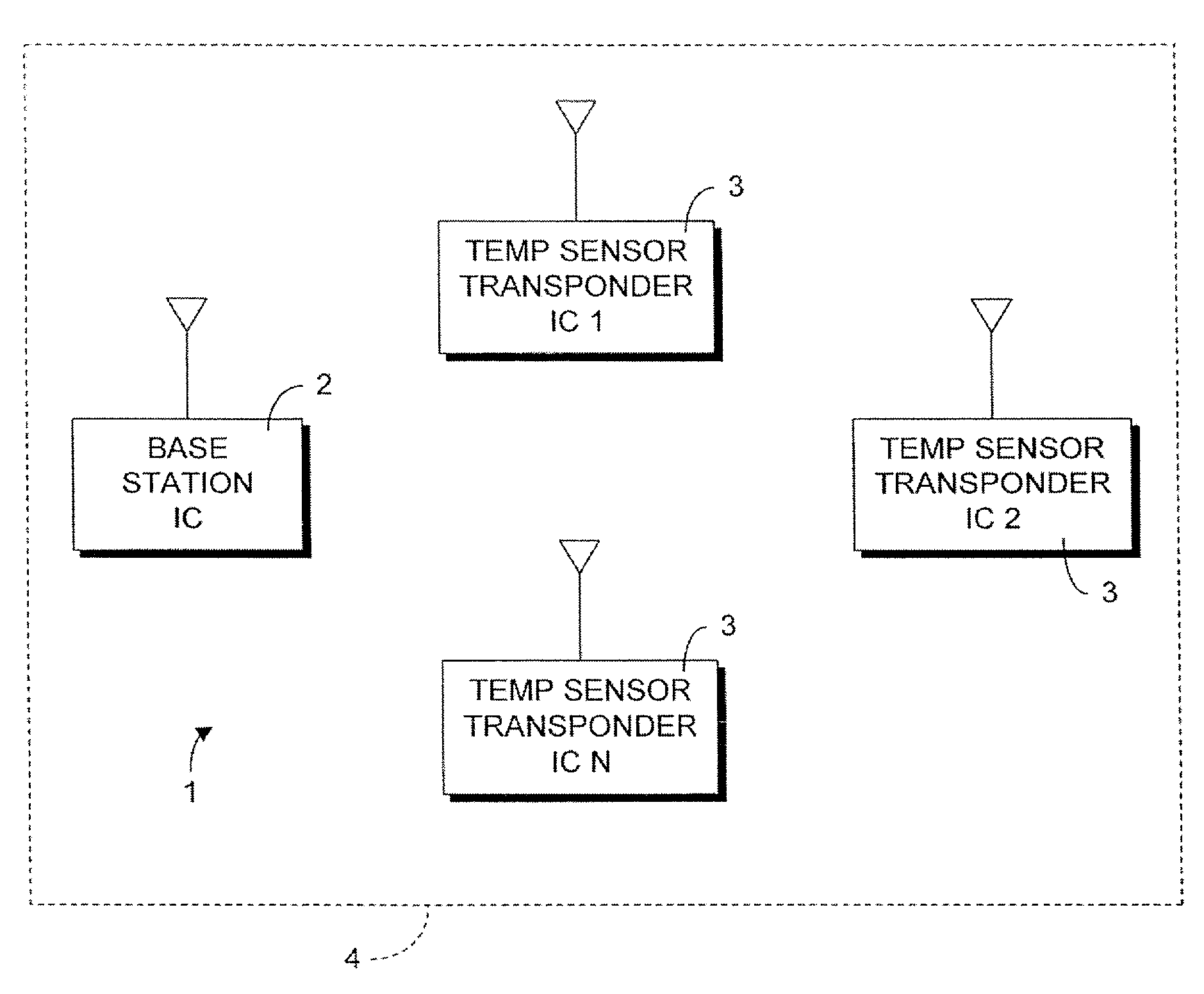
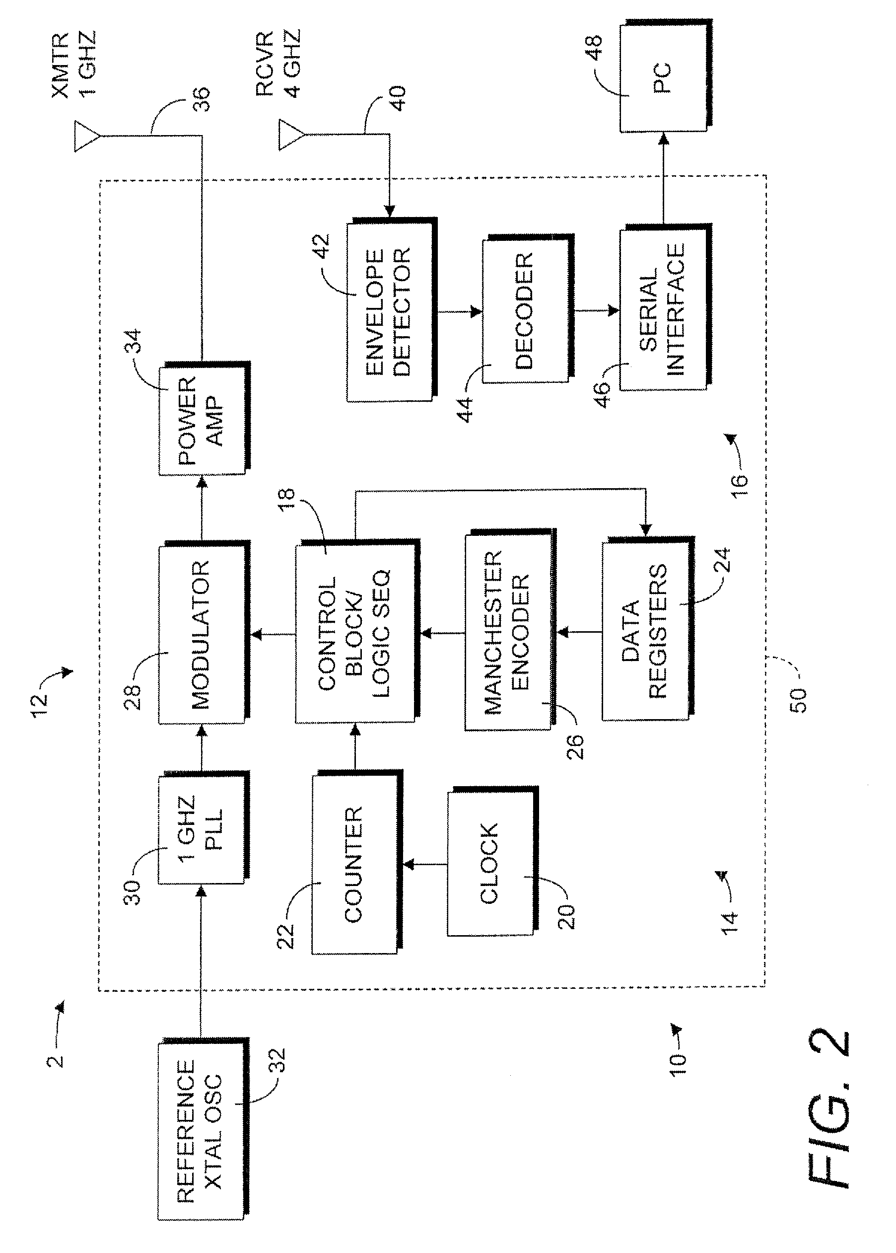
[0021]Referring to the drawings in more detail, the reference numeral 1 generally designates an embodiment of a wireless temperature sensor network according to the present invention. The network 1 generally includes a base station unit 2 and a plurality of temperature sensor transponder units 3. In general, the transponder units 3 are passive and derive operating power from a querying signal transmitted by the base station 2. The transponder units 3 are indi...


PUM


Abstract

A wireless temperature sensor network includes a base station unit which transmits query signals cyclically addressing a plurality of temperature sensor transponder units. The transponder units are passive and derive operating power from the query signal to encode measured temperature data into a reply signal which is received by the base station. In a dual carrier embodiment, the query signal and reply signals are transmitted on separate frequencies. In a backscattering embodiment, the antennas of the transponder units can be switched between an absorption mode in which the query signal is received and a reflection mode in which the query signal is reflected back to the base station. The transponder antennas are switched in such a manner as to encode temperature data in the reflected signal to form a reply signal. The network embodiments are particularly applicable to space based platforms.

Description

FIELD OF THE INVENTION[0001]The present invention is generally directed to wireless networks and, more particularly, to wireless networks of temperature sensors and other types of sensors with advantageous application to space based platforms.BACKGROUND OF THE INVENTION[0002]Space vehicles require that certain parameters be sensed and monitored to detect impending faults, to detect and respond to certain conditions, and to maintain desired environments for operating equipment. For example, typical space borne electronic systems require the temperature to be sensed at many points so that the effects of temperature can be compensated for. Sensors for temperature, along with pressure and other parameters are, therefore, positioned at various locations within a space vehicle. The sensors are linked to a controller, such as a computer, for periodic reading and recording of measured values. The sensors are often interfaced to address circuitry which is networked to the computer so that th...

Claims


Application Information

Patent Timeline
Patent Type & Authority Applications(United States)
IPC IPC(8): G08B1/08
CPCG01D21/00G01K1/026G01K1/024
Inventor TAYRANI, REZAYOUNG, RICHARD D.ROSIK, NICK J.STADING, MARK E.CHAMPION, SHAUN L.PHILIP, IVES H.NGUYEN, THO X.
Owner RAYTHEON CO
Learn More