Microfluidic devices and methods

a microfluidic device and microfluidic technology, applied in the direction of radiation measurement, spectral modifiers, optical radiation measurement, etc., can solve the problem of one or more defective reaction cells, and achieve the effect of reducing mixing times, reducing dehydration of microfluidic devices, and increasing manufacturing yield rates

Active Publication Date: 2010-09-16
STANDARD BIOTOOLS INC
View PDF77 Cites 140 Cited by
  • Summary
  • Abstract
  • Description
  • Claims
  • Application Information

AI Technical Summary

Benefits of technology

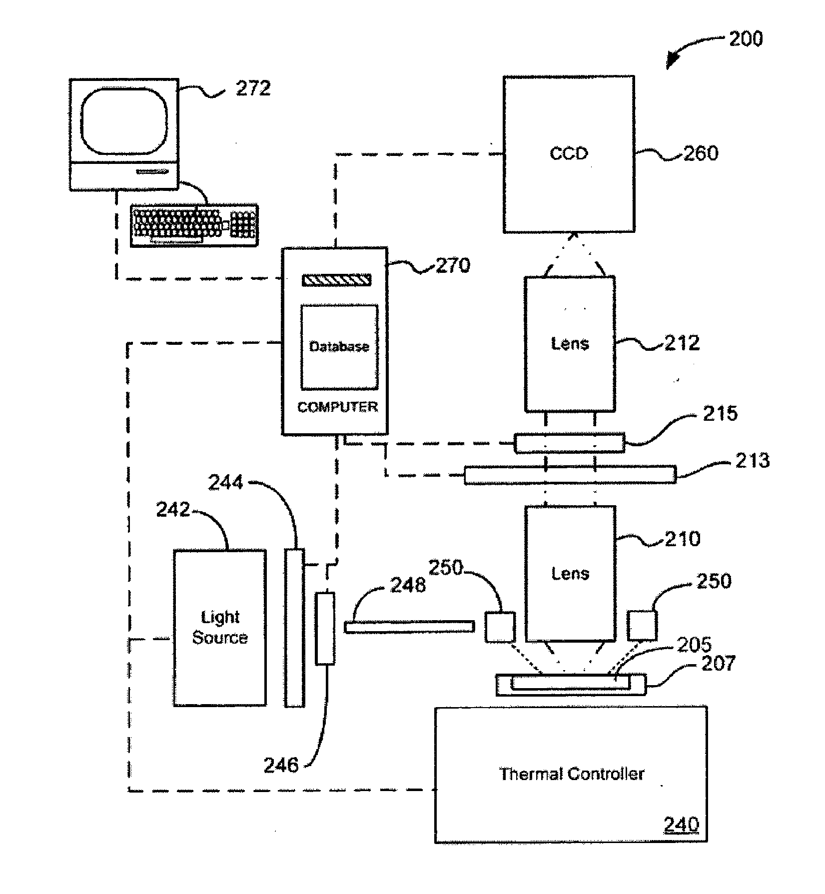
[0012]Embodiments of the present invention provide improved microfluidic devices and related apparatuses, systems, and methods. Methods are provided for reducing mixing times during use of microfluidic devices. Microfluidic devices and related methods of manufacturing are provided with increased manufacturing yield rates. Improved apparatuses and related systems are provided for supplying controlled pressure to microfluidic devices. Methods and related microfluidic devices are provided for reducing dehydration of microfluidic devices during use. Microfluidic devices and related methods are provided with improved sample to reagent mixture ratio control. Microfluidic devices and systems are provided with improved resistance to compression fixture pressure induced failures. Methods and systems for conducting temperature controlled reactions using microfluidic devices are provided that reduce condensation levels within the microfluidic device. Methods and systems are provided for improved fluorescent imaging of microfluidic devices. Reduced mixing times lowers both time and related costs for the analysis being conducted. Microfluidic devices with increased manufacturing yield rates lower costs and help to minimize waste. Improved apparatus and systems for supplying controlled pressure to microfluidic devices help to simplify microfluidic device processing equipment, thereby reducing costs. Decreased microfluidic device dehydration helps to minimize detrimental impacts that occur when water escapes from reaction fluids, especially from sample fluids that contain significant relative amounts of water. Improved sample to reagent mixture ratio control helps to increase processing effectiveness. Lower rates of compression fixture pressure induced failure help to increase the success rate achieved during temperature controlled reactions. Improved fluorescent imaging helps to increase the certainty by which analysis results can be determined.Reduced Mixing Times
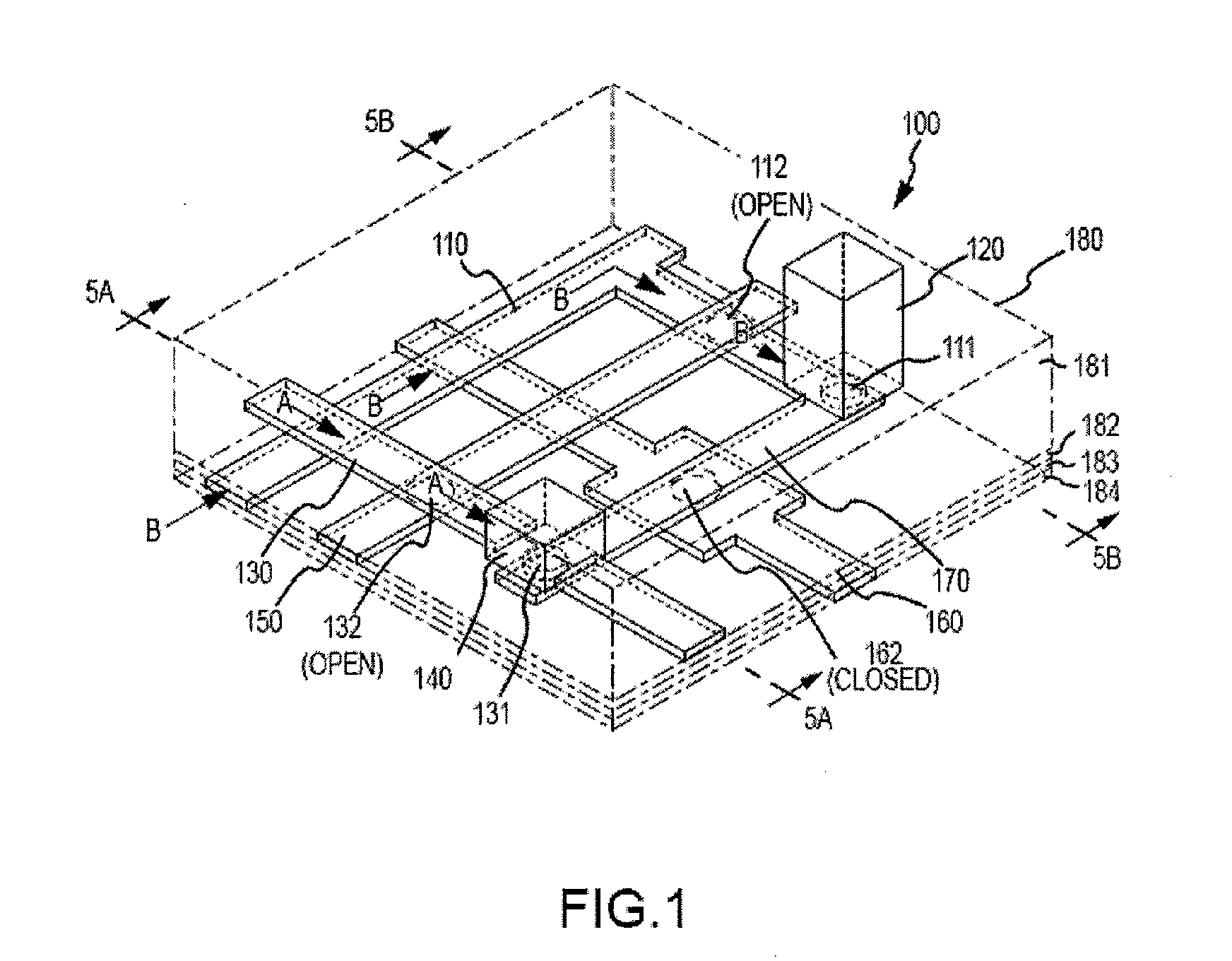
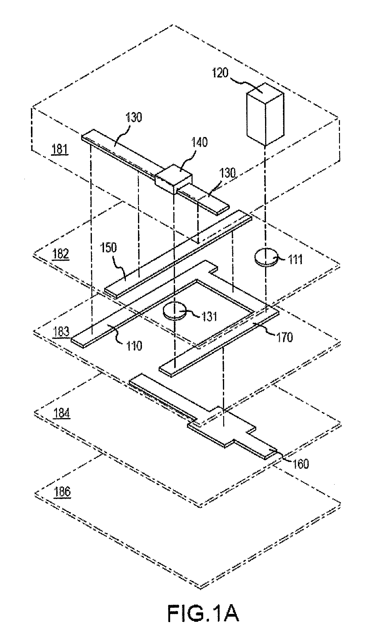
[0013]Thus, in one aspect, embodiments of the present invention provide methods for reducing mixing time for a mixture of a sample fluid and a reagent fluid. A method can, for example, involve a microfluidic device having a reaction cell that includes a sample chamber and a reagent chamber that are in fluid communication through an interface channel having an interface valve. Sample fluid can be introduced into the sample chamber at a first pressure and reagent fluid can be introduced into the reagent chamber at a second pressure. The sample fluid and the reagent fluid can be mixed by opening the interface valve. The first pressure and the second pressure can be sufficiently different to cause the mixing to occur at least in part by fluid injection. In some embodiments, the sample chamber pressure is greater than the reagent chamber pressure, and can be greater by 1.0 psi. In other embodiments, the reagent chamber pressure is greater than the sample chamber pressure, and can be greater by 1.0 psi. Often, a microfluidic device reaction cell will be configured with a sample chamber volume being greater than a reagent chamber volume, but can also be configured with a reagent chamber volume being equal to or greater than a sample chamber volume.Increased Manufacturing Yield Rates
[0014]In another aspect, embodiments of the present invention provides microfluidic devices with increased manufacturing yield rates, and related methods for manufacturing. A device can include, for example, a configuration that allows for the isolation of defective reaction cells. During the manufacture of a microfluidic device, manufacturing defects may result in one or more defective reaction cells. Often, these defective cells can be identified during quality control inspections. Embodiments of the present invention provide microfluidic devices that can be configured so as to isolate one or more reaction cells, including one or more identified defective reaction cells. The device can include a first flow channel for introduction of a fluid via an inlet to the first reaction cell and a second flow channel for introduction of a fluid via the inlet to the second reaction cell. A microfluidic device can be configurable to have the inlet in fluid communication with the first flow channel, and fluidically separated from the second flow channel. Often, the device will also be configurable to have the inlet in fluid communication with the second flow channel and fluidically separated from the first flow channel. In some embodiments, each of the first flow channel and the second flow channel is initially in fluid communication with the inlet, and the device includes a first fusible isolation feature and a second fusible isolation feature, the first fusible isolation feature being configurable to fluidically separate the first flow channel from the inlet, and the second fusible isolation feature being configurable to fluidically separate the second flow channel from the inlet. In some embodiments, each of the first and second fusible isolation features is a containment valve that is fusible by an exposure of ultraviolet light. The first and second flow channels can be for the introduction of a sample fluid. Alternatively, the first and second flow channels can be for the introduction of a reagent fluid.

Problems solved by technology

During the manufacture of a microfluidic device, manufacturing defects may result in one or more defective reaction cells.

Method used


Image

  • Microfluidic devices and methods
  • Microfluidic devices and methods
  • Microfluidic devices and methods

Examples


Embodiment Construction

[0068]The present invention relates generally to microfluidic devices and related apparatus, systems, and methods. In particular, methods are provided for reducing mixing times during use of microfluidic devices. Microfluidic devices and related methods of manufacturing are provided with increased manufacturing yield rates. Improved apparatus and related systems are provided for supplying controlled pressure to microfluidic devices. Methods and related microfluidic devices are provided for reducing dehydration of microfluidic devices during use. Microfluidic devices and related methods are provided with improved sample to reagent mixture ratio control. Microfluidic devices and systems are provided with improved resistance to compression fixture pressure induced failure. Methods and systems for conducting temperature controlled reactions using microfluidic devices are provided that reduce condensation levels within the microfluidic device. Methods and systems are provided for improve...


PUM

PropertyMeasurementUnit
Angleaaaaaaaaaa
Ratioaaaaaaaaaa
Fluorescenceaaaaaaaaaa

Abstract

Embodiments of the present invention provide improved microfluidic devices and related apparatus, systems, and methods. Methods are provided for reducing mixing times during use of microfluidic devices. Microfluidic devices and related methods of manufacturing are provided with increased manufacturing yield rates. Improved apparatus and related systems are provided for supplying controlled pressure to microfluidic devices. Methods and related microfluidic devices are provided for reducing dehydration of microfluidic devices during use. Microfluidic devices and related methods are provided with improved sample to reagent mixture ratio control. Microfluidic devices and systems are provided with improved resistance to compression fixture pressure induced failures. Methods and systems for conducting temperature controlled reactions using microfluidic devices are provided that reduce condensation levels within the microfluidic device. Methods and systems are provided for improved fluorescent imaging of microfluidic devices.

Description

CROSS-REFERENCES TO RELATED APPLICATIONS[0001]This application is a nonprovisional of, and claims the benefit of priority to, U.S. Patent Application No. 61 / 145,459, filed Jan. 16, 2009, the entire content of which is incorporated herein by reference for all purposes.BACKGROUND OF THE INVENTION[0002]The present invention relates generally to microfluidic devices, which provide for precise control and manipulation of fluids that are geometrically constrained to a small, typically sub-millimeter, scale. In particular, the invention provides microfluidic devices and related apparatus, systems, and methods.[0003]Recently, there have been concerted efforts to develop and manufacture microfluidic systems to perform various chemical and biochemical analyses and syntheses, both for preparative and analytical applications. The goal to make such devices arises because of the significant benefits that can realized from miniaturization with respect to analyses and syntheses conducted on a macro...

Claims


Application Information

Patent Timeline
IPC IPC(8): G01J1/58
CPCB01L3/502738B01L7/52B01L2200/16B01L2300/0867B01L2300/0874C12Q1/686B01L2400/0481B01L2400/0655G01N21/05G01N21/6452G01N2021/0346B01L2300/123Y10T137/7793Y10T436/2575B33Y80/00G01N1/28
Inventor PIEPRZYK, MARTINFACER, GEOFFWOUDENBERG, TIMOTHYFOWLER, BRIAN
Owner STANDARD BIOTOOLS INC
Why Eureka
Try Eureka