
Cutouts with automatic reclosing

a cutting-out and automatic reclosing technology, applied in the direction of circuit-breaking switch details, protective switch details, protective switch operating/release mechanisms, etc., can solve the problems if properly functioning, deficiency, etc., and achieve the effect of preventing blown fuse elements, reducing the risk of blown fuse elements, and reducing the service li

Active Publication Date: 2010-09-16
ABB (SCHWEIZ) AG
View PDF6 Cites 9 Cited by
  • Summary
  • Abstract
  • Description
  • Claims
  • Application Information

AI Technical Summary

Benefits of technology

The present invention provides a cutout for use in an electrical distribution network to connect two electrical cables. The cutout includes an insulator, terminal assemblies, and a reclosing mechanism. The reclosing mechanism includes an engaging arm that can be moved between a contact position and a release position. The engaging arm secures the fuse assembly in an engaged position to conduct electricity between the two cables upon detection of a fault condition. The cutout also includes a failsafe fuse assembly that can be opened and closed multiple times to monitor the electrical current through the fuse assembly. The cutout is designed to provide a safe and reliable connection between the two cables and to protect against fault conditions.

Problems solved by technology

Due to the nature of electrical transmission and the unpredictability of outside influences (eg. lightning), protective devices are used to protect power distribution equipment from damage caused by excessive voltages and / or currents.
Though such designs have proven effective in protecting power distribution equipment, deficiencies do exist.
However, the fuse element, if properly functioning, is now blown and requires a utility service person to travel to the cutout, replace the fuse element, and reposition it to close the circuit.
This takes a substantial period of time, and all the while, downstream customers remain without power.
Further, putting numerous service persons out into the field, particularly during inclement weather, is both dangerous and expensive.

Method used


Image

  • Cutouts with automatic reclosing
  • Cutouts with automatic reclosing
  • Cutouts with automatic reclosing

Examples


Embodiment Construction

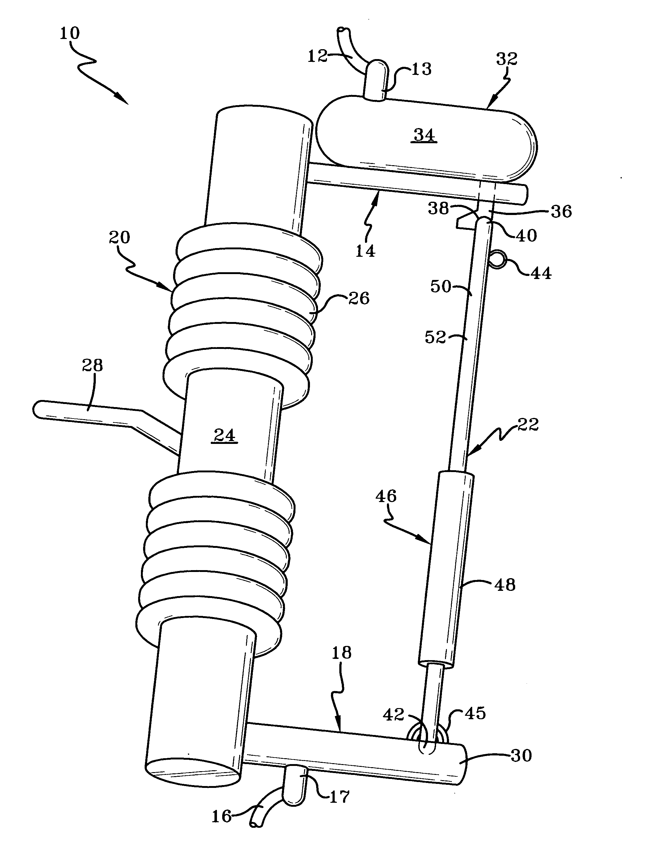
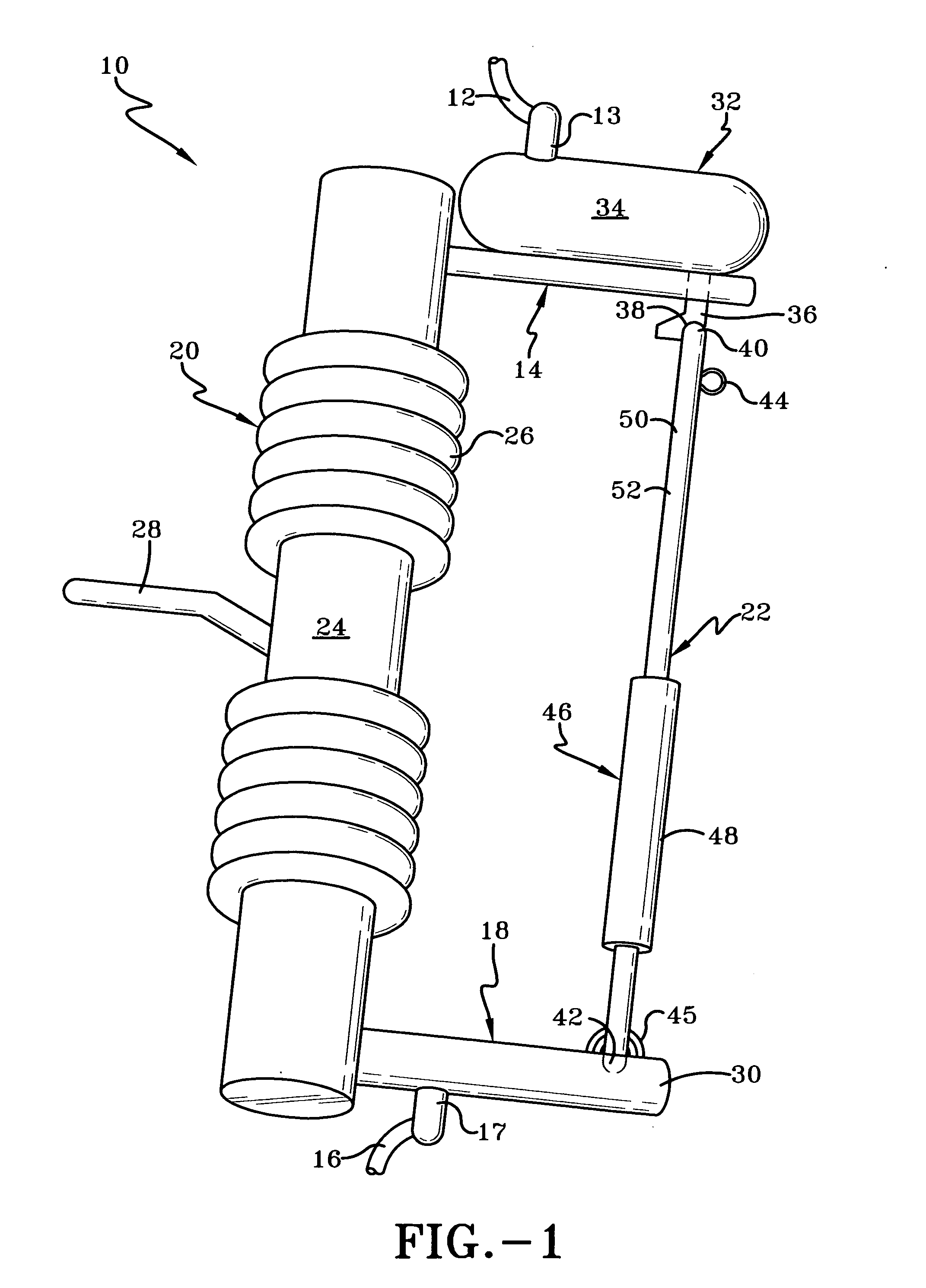
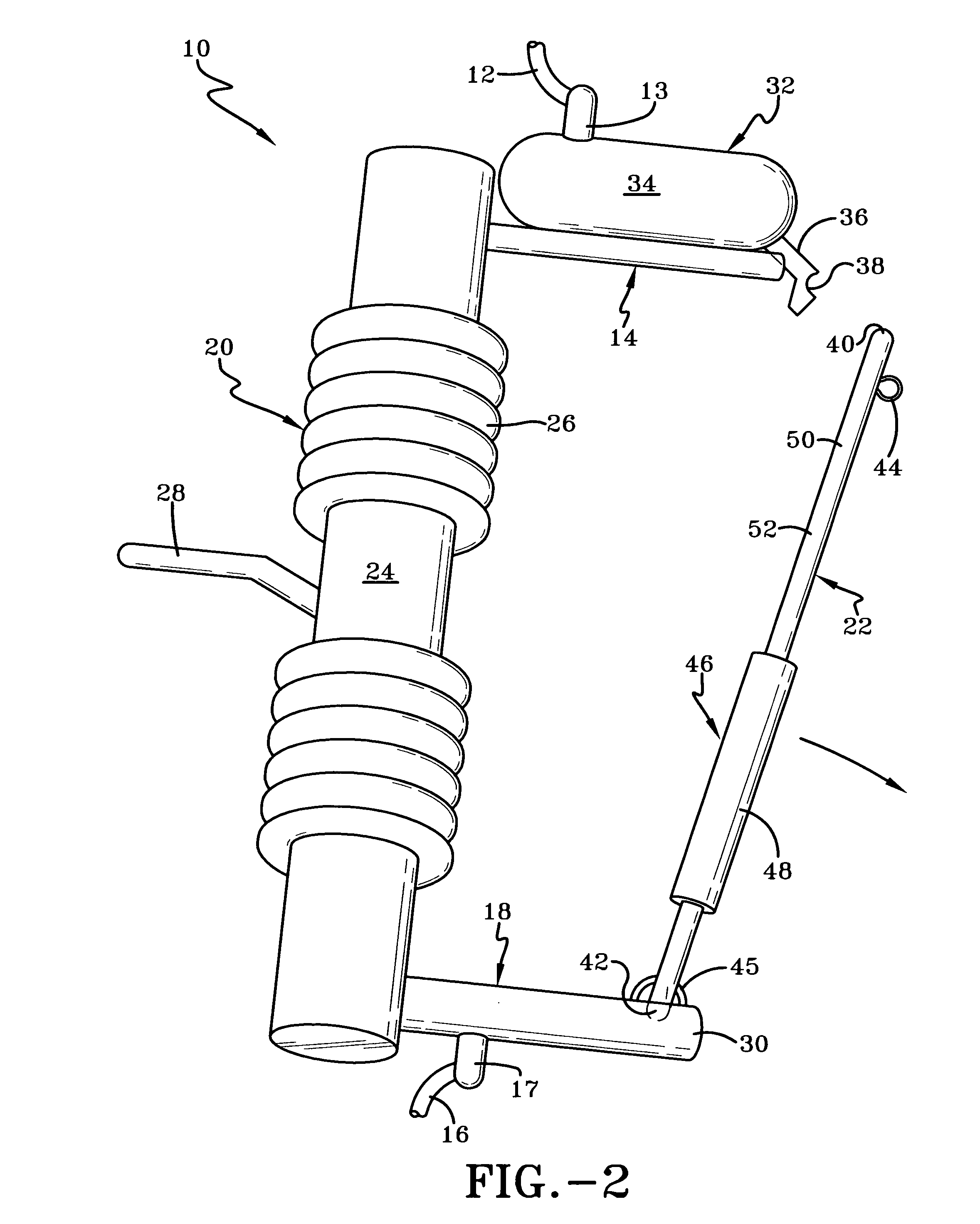
[0026]Referring now to FIG. 1, a first exemplary cutout, according to the present invention, is disclosed and generally indicated by the numeral 10. A first high voltage power line or electrical cable 12 is secured to the mounting bracket 13 of an upper line terminal assembly 14 (hereinafter upper terminal) and a second high voltage power line or electrical cable 16 is secured to the mounting bracket 17 of a lower line terminal assembly 18 (hereinafter lower terminal). Upper and lower terminals 14 and 18 are spaced by an insulator 20 and a fuse assembly 22.

[0027]Insulator 20 has an elongated central stem portion 24 defining a longitudinal direction, and a plurality of longitudinally spaced apart skirts 26 extending from stem portion 24. As is known in the art, insulator 20 is composed of non-electrically conductive materials and is attached to a pole or other support structure via bracket 28.

[0028]Insulator 20 essentially serves as a holder for fuse assembly 22, and under normal ope...


PUM


Abstract

A cutout is used in an electrical distribution network to electrically connect a first electric cable with a second electrical cable, The cutout includes an electrically non-conductive insulator having first and second end. A first terminal assembly is secured to the first insulator end. A second terminal assembly is secured to the second insulator end. A failsafe fuse assembly is pivotally secured to the second terminal and is movable between an engaged position and a lockout position. A reclosing mechanism is secured to the first terminal and monitors electrical current through the fuse assembly. If a fault condition exists, the reclosing mechanism opens and then closes the electrical link between the first and second electrical cable. If, after a predetermined number of closes, the fault condition still exists, the reclosing mechanism disconnects from the fuse assembly, allowing the fuse assembly to fall to the lockout position.

Description

CROSS REFERENCE TO RELATED APPLICATION[0001]This application claims the priority of U.S. provisional patent application Ser. No. 60 / 952,088 filed on Jul. 26, 2007, entitled “Cutouts with Automatic Reclosing” the contents of which are relied upon and incorporated herein by reference in their entirety, and the benefit of priority under 35 U.S.C. 119(e) is hereby claimed.FIELD OF THE INVENTION[0002]This invention relates to electrical distribution equipment and more particularly to fault protection equipment for use in an electrical distribution network.DESCRIPTION OF THE PRIOR ART[0003]Due to the nature of electrical transmission and the unpredictability of outside influences (eg. lightning), protective devices are used to protect power distribution equipment from damage caused by excessive voltages and / or currents. One such protective device is known as a cutout, which functions to open a circuit when electric current in the circuit exceeds a predetermined level.[0004]Typically, cuto...

Claims


Application Information

Patent Timeline
Patent Type & Authority Applications(United States)
IPC IPC(8): H01H31/02
CPCH01H31/127H01H33/027H02H3/07H01H71/70H01H75/04H01H33/125
Inventor HAJ-MAHARSI, MOHAMED Y.
Owner ABB (SCHWEIZ) AG
Learn More