
Apparatus for Burning Organic Substances

a technology of organic substances and apparatuses, which is applied in the direction of indirect carbon-dioxide mitigation, combustion process, lighting and heating apparatus, etc., can solve the problem that the temperature progression cannot have any disadvantageous influence on the combustion conditions in the combustion chamber, and achieve the effect of simple construction effort and favorable utilization of sensible waste hea

Inactive Publication Date: 2010-09-09
FRELLER WALTER
View PDF38 Cites 4 Cited by
  • Summary
  • Abstract
  • Description
  • Claims
  • Application Information

AI Technical Summary

Benefits of technology

[0003]The invention is thus based on the object of providing an apparatus for burning organic substances of the kind mentioned above in such a way that by maintaining advantageous combustion conditions a favorable utilization of the sensible waste heat of the hot exhaust gases from the combustion chamber is obtained, with a comparatively simple constructional effort.
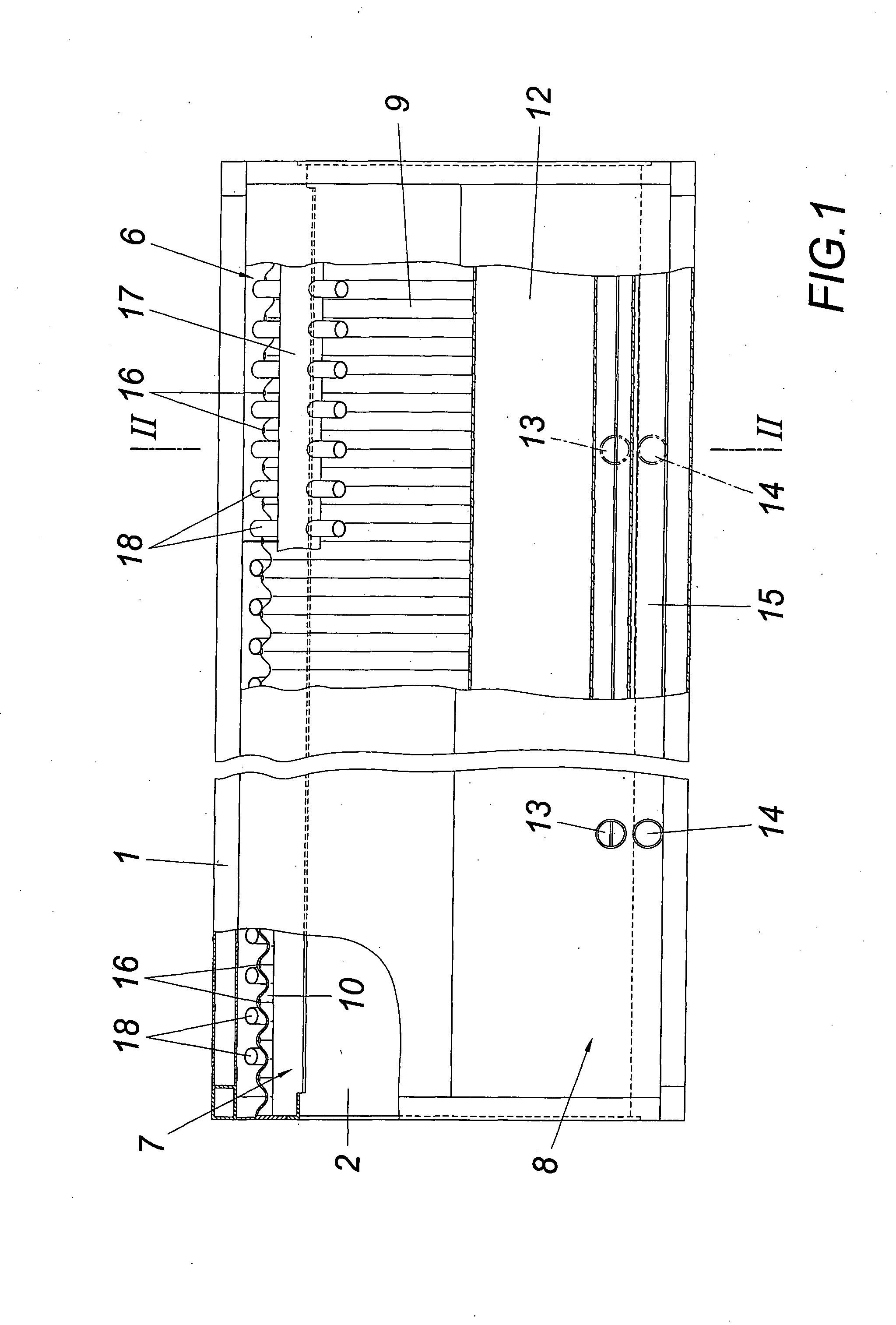
[0005]Since the counter-flow heat exchanger encloses the combustion chamber outside of its heat insulation for preheating the combustion air, the temperature progression cannot have any disadvantageous influence on the combustion conditions in the combustion chamber during the heating of the combustion air. An additional factor is that the sensible waste heat of the exhaust gases flowing through an upper exhaust gas outlet from the combustion chamber into the housing can be utilized advantageously for the heating of a heat-transfer medium without having to omit the required preheating of the combustion air. It is merely necessary to provide respective heat exchangers in the interstices which are obtained on either side of the cylindrical combustion chamber and the prismatic housing, which heat exchangers are flowed around by hot exhaust gases emerging from the combustion chamber. When the exhaust gases are withdrawn from the interstices by the counter-flow heat exchanger for the combustion air, sufficient preheating of the combustion air is ensured, especially when the heat-exchanger wall extends in the circumferential direction of the combustion chamber into the interstices, so that a respective extension of the flow duct for the combustion air is achieved. An additional heat exchange occurs between the hot exhaust gases in the interstices and the combustion air guided through the flow duct via the heat-exchanger wall of the counter-flow heat exchanger extending into the interstices of the housing.
[0007]In order to obtain simple constructional conditions also for the heat exchangers for heating the heat-transfer medium, the heat exchangers can comprise a flow pipe for the heat-transfer medium parallel to the axis of the combustion chamber in the interstices of the housing, which flow pipe is radially penetrated with pipe connection pieces for the exhaust gas guidance. As a result of these constructional measures, not only the flow pipes for the heat-transfer medium form a heat-exchanger surface, but also the pipe connection pieces which radially penetrate the flow pipes, which connection pieces are flowed through by hot exhaust gases flowing into the interstices of the housing, especially when they are adjusted with respect to their inclination to the flow conditions obtained in the interstices. The flow rate can also be improved by guide surfaces for the exhaust gas flow in the interstices.

Problems solved by technology

Since the counter-flow heat exchanger encloses the combustion chamber outside of its heat insulation for preheating the combustion air, the temperature progression cannot have any disadvantageous influence on the combustion conditions in the combustion chamber during the heating of the combustion air.

Method used


Image

  • Apparatus for Burning Organic Substances
  • Apparatus for Burning Organic Substances
  • Apparatus for Burning Organic Substances

Examples


Embodiment Construction

[0011]The apparatus for burning organic substances, especially garbage, comprises a prismatic housing 1 with a rectangular cross section and a substantially cylindrical combustion chamber 2 with a horizontal axis. Said combustion chamber is provided with a heat insulation 3 which screens the combustion chamber from the housing 1. As a result of the arrangement of a substantially cylindrical combustion chamber 2 in a prismatic housing 1 with rectangular cross section, interstices 4, 5 are obtained in the corner regions of the housing 1 between the combustion chamber 2 and the housing 1, of which the upper interstices 4 situated on either side of the combustion chamber 3 receive heat exchangers 6 for a heat-transfer medium, which heat exchangers extend parallel to the combustion chamber 2.

[0012]The hot exhaust gases exit from the combustion chamber 2 through an exhaust-gas outlet 7 which is provided in the apex region of the combustion chamber 2 and extends substantially over the axia...


PUM


Abstract

An apparatus is described for burning organic substances, comprising a horizontal combustion chamber (2) provided in a housing (1) and heat-insulated against said housing (1), and a counter-flow heat exchanger (8) which preheats the combustion air with the help of the hot exhaust gases from the combustion chamber (2) and which forms a flow duct (10) for the combustion air between the combustion chamber (2) and a heat-exchanger wall (9) enclosing the combustion chamber (2), as well as a flow duct (11) for the hot exhaust gases on the side of the heat-exchanger wall (9) averted from the combustion chamber (2). In order to provide advantageous constructional conditions it is proposed that the heat-exchanger wall (9) of the counter-flow heat exchanger (8) is provided on the outside of the heat insulation (3) of the combustion chamber (2) which comprises an upper exhaust outlet (7) opening into the housing (1), that heat exchangers (6) which extend parallel to the combustion chamber (2) are provided for the heating of a heat-transfer medium with the sensible waste heat of the hot exhaust gases in the upper interstices (4) obtained on either side of the cylindrical combustion chamber (2) between the combustion chamber (2) and the substantially prismatic housing (1), and that the exhaust-gas-receiving flow duct (11) of the counter-flow heat exchanger (8) for the exhaust gases originates from the two interstices (4), while the heat-exchanger wall (9) extends with the flow duct (10) for the combustion air into the interstices (4).

Description

1. FIELD OF THE INVENTION[0001]The invention relates to an apparatus for burning organic substances, comprising a horizontal combustion chamber provided in a housing and heat-insulated against said housing, and a counter-flow heat exchanger which preheats the combustion air with the help of the hot exhaust gases from the combustion chamber and which forms a flow duct for the combustion air between the combustion chamber and a heat-exchanger wall enclosing the combustion chamber, as well as a flow duct for the hot exhaust gases on the side of the heat-exchanger wall averted from the combustion chamber.2. DESCRIPTION OF THE PRIOR ART[0002]In order to burn organic substances, and garbage in particular, it is known (U.S. Pat. No. 5,315,938 A) to provide the combustion chamber which is provided in a housing, is situated horizontally and supplied axially with a heat insulation against the housing receiving a liquid heat-transfer medium in order to ensure advantageous combustion conditions...

Claims


Application Information

Patent Timeline
IPC IPC(8): F23L15/00F23B80/04
CPCF23L15/00F23B80/04Y02E20/34
Inventor FRELLER, WALTER
Owner FRELLER WALTER
Learn More