Diffuser arrangement

a diffuser and arrangement technology, applied in the direction of machines/engines, stators, liquid fuel engines, etc., can solve the problems of principally prone separation of the inner surface of the outer diffuser, and achieve the effect of low flow resistance and cost-effective production

Inactive Publication Date: 2010-09-09
SIEMENS AG
View PDF2 Cites 25 Cited by
  • Summary
  • Abstract
  • Description
  • Claims
  • Application Information

AI Technical Summary

Benefits of technology

[0036]As a result, the guide plate can advantageously be cost-effectively produced.
[0037]Alternatively to this, it is preferr

Problems solved by technology

If the fluid flows through the outer diffuser, then it is decelerated in the main flow direction, as a result of which

Method used


Image

  • Diffuser arrangement
  • Diffuser arrangement
  • Diffuser arrangement

Examples


Embodiment Construction

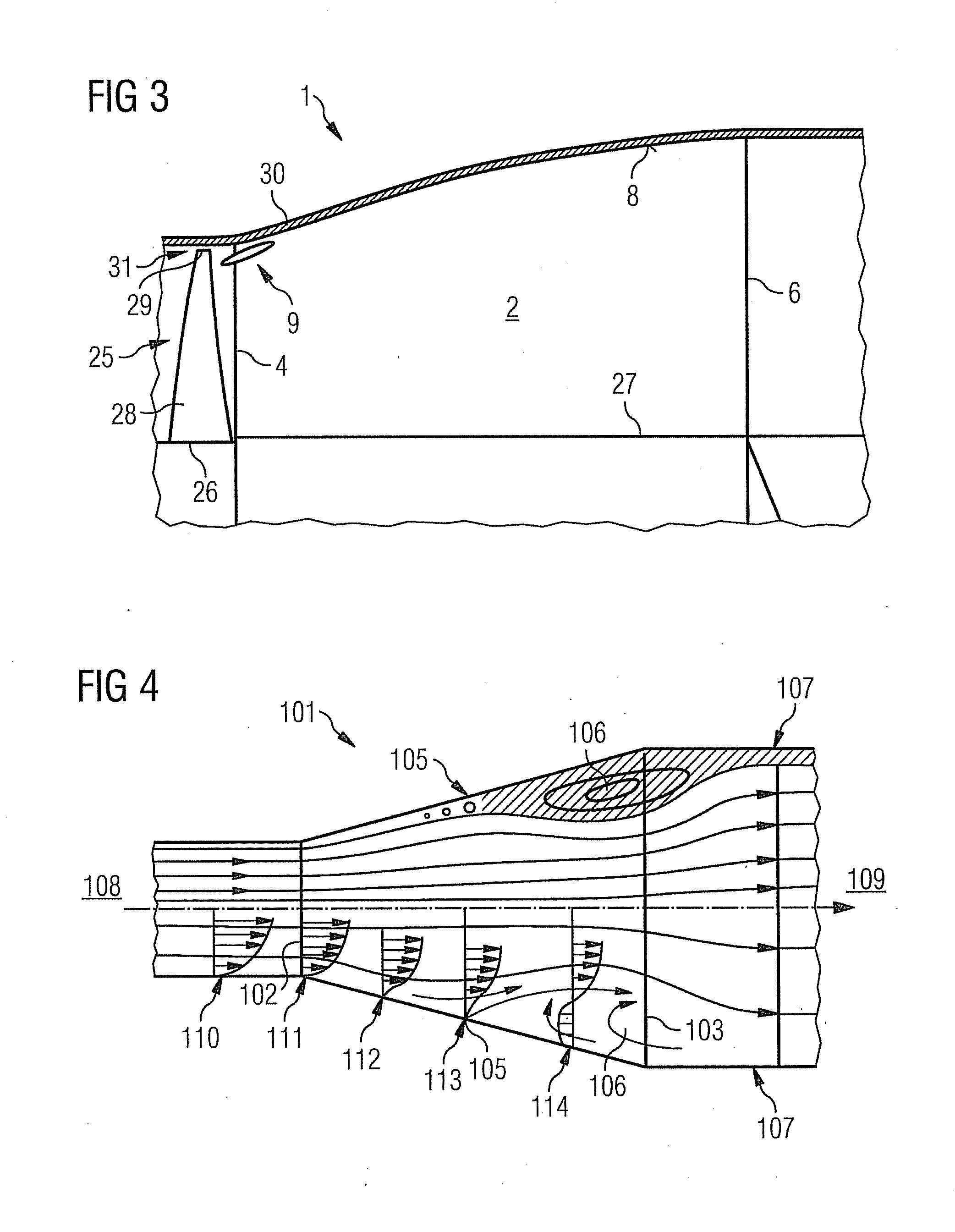
[0051]As is apparent from FIG. 1, a diffuser arrangement 1 has an outer diffuser 2 which is axially symmetrically formed around its symmetry axis 3. An inlet cross section 4 of the outer diffuser 2, through which an inflow 5 flows into the outer diffuser 2, lies in a plane which is perpendicular to the symmetry axis 3, and its outlet cross section 6, from which an outflow 7 discharges from the outer diffuser 2, lies in another plane which is perpendicular to the symmetry axis 3 of the outer diffuser 2. This outer diffuser has an inner surface 8 which delimits the inside space of the said outer diffuser 2.

[0052]The outer diffuser 2 is formed as a straight diffuser, i.e. the inner surface 8 of the outer diffuser 2 forms a truncated cone, wherein the cross-sectional area at the inlet cross section 4 is smaller than the cross-sectional area at the outlet cross section 6.

[0053]A flow-guiding device 9 is arranged inside the outer diffuser 2. The flow-guiding device 9 is formed as a guide ...


PUM


Abstract

A diffuser arrangement through which a fluid may flow is provided. The diffuser includes an outer diffuser comprising an inner surface, and a flow-guiding device, which is configured such that at least part of the boundary layer flow forming on the inner surface of the outer diffuser can be accelerated in the main flow direction, so that a flow separation is prevented on the inner surface of the outer diffuser. Also provided are an exhaust steam plenum of a steam turbine and an exhaust gas plenum of a gas turbine, both including a diffuser arrangement.

Description

CROSS REFERENCE TO RELATED APPLICATIONS[0001]This application is the US National Stage of International Application No. PCT / EP2008 / 052222, filed Feb. 25, 2008 and claims the benefit thereof. The International Application claims the benefits of European Patent Office application No. 07005175.0 EP filed Mar. 13, 2007, both of the applications are incorporated by reference herein in their entirety.FIELD OF INVENTION[0002]The invention refers to a diffuser arrangement and especially to an exhaust steam plenum of a steam turbine or an exhaust gas plenum of a gas turbine with the diffuser arrangement.BACKGROUND OF INVENTION[0003]A diffuser is a passage which is exposable to throughflow by fluid and which in the case of separation-free throughflow decelerates the fluid by means of cross-sectional widening and, in accordance with Bernoulli's theorem, reduces the kinetic pressure of the fluid to the benefit of the static pressure.[0004]The quality of the diffuser is described by means of the...

Claims


Application Information

Patent Timeline
IPC IPC(8): F04D29/44
CPCF01D9/02F01D25/30F15D1/0005F15D1/0025F05D2250/292F05D2220/31F05D2220/32F05D2250/323F05D2250/232F15D1/06
Inventor BECKER, SASCHABROKER, MARCHOFFACKER, RALFKOEBE, MARIOMAHLMANN, STEFANSTANKA, ULRICH
Owner SIEMENS AG
Why Eureka
Try Eureka