Barrier unit

a barrier unit and unit technology, applied in the field of barriers, can solve the problems of affecting the operation of the barrier unit, the failure of the opening and closing of the blades, and the possibility so as to suppress the occurrence of flare and ghosting caused by reflection of light, and facilitate conta

Inactive Publication Date: 2010-09-09
PANASONIC CORP
View PDF8 Cites 7 Cited by
  • Summary
  • Abstract
  • Description
  • Claims
  • Application Information

AI Technical Summary

Benefits of technology

[0011]According to the barrier unit of the first aspect, since an inclined portion is provided at a central portion in a longitudinal direction of each predetermined end face of the blades, the inclined portion defining a plane inclined with respect to an optical axis of a lens, reflection of light at the predetermined end faces of the blades is suppressed. Accordingly, the occurrence of flare and ghosting caused by reflection of light can be suppressed. Furthermore, since a parallel portion is provided on both sides of the inclined portion of each predetermined end face of the blades, the parallel portion defining a plane parallel to the optical axis, when the blades are in a closed state the predetermined end faces contact each other. Thus, the occurrence of operation failures due to the blades riding on top of each other when the blades are in a closed state can be suppressed.

Problems solved by technology

For example, as shown in FIG. 12, when the blades 2 and 3 are in an open state, light C incident through the barrier unit reflects off the end faces 2a and 3a and the reflected light incident through a barrel, so that optical problems such as flare and ghosting may occur.
However, setting the amount of retreat d to a large value inhibits miniaturization of the barrier unit.
That is, there is a problem that a failure of opening and closing of the blades 2 and 3 is likely to occur.

Method used


Image

  • Barrier unit
  • Barrier unit
  • Barrier unit

Examples


first embodiment

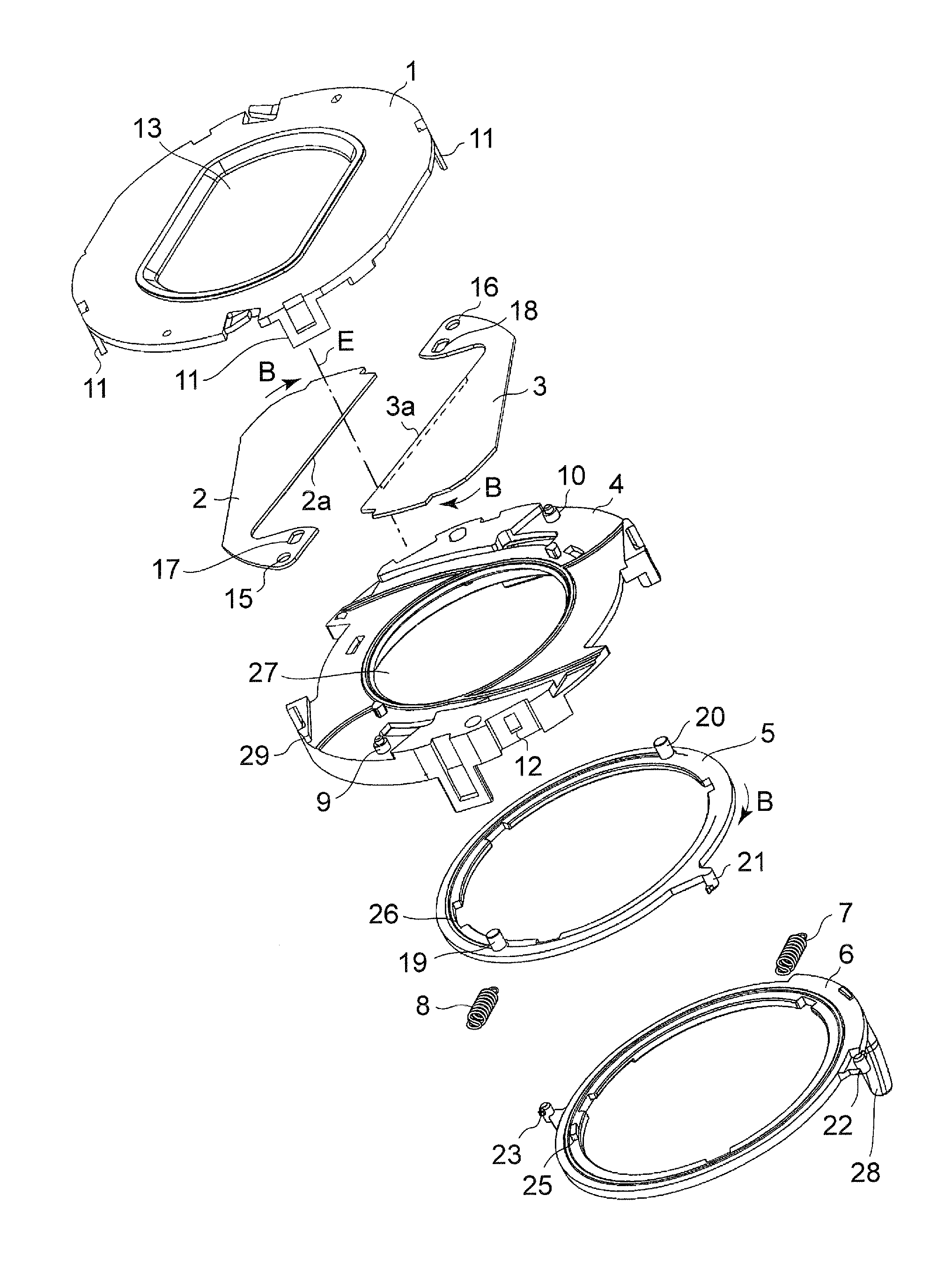
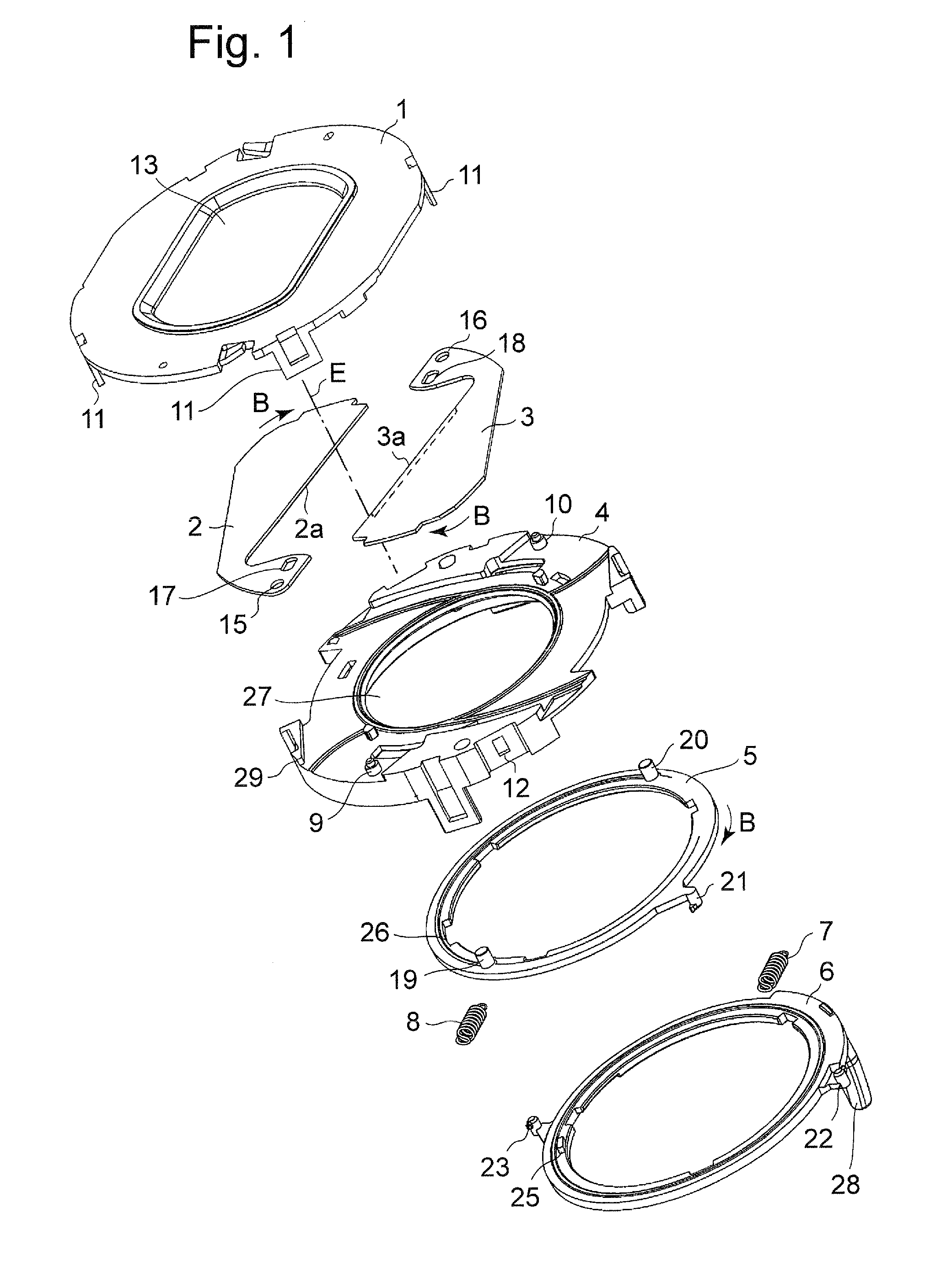
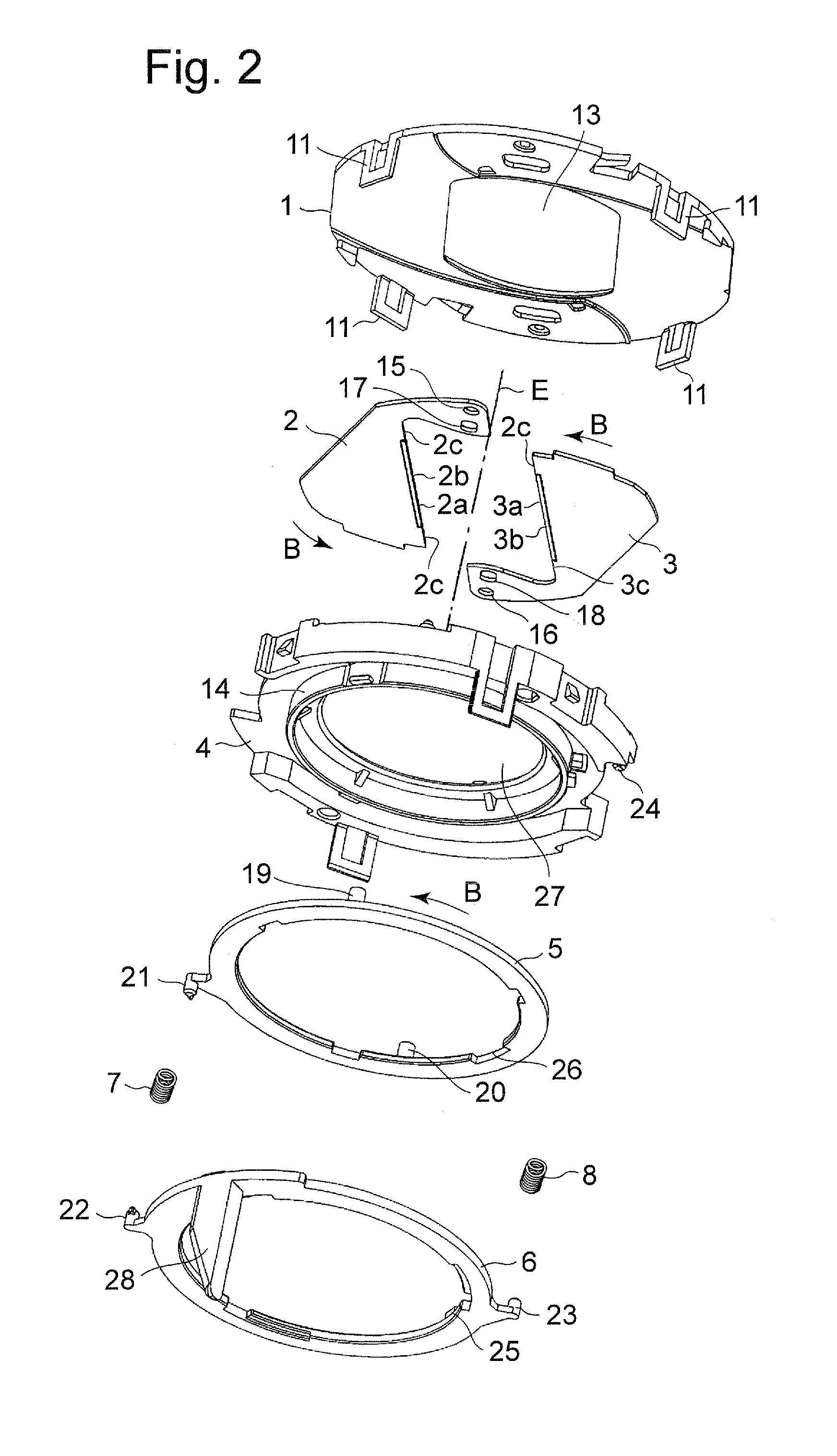
[0026]FIG. 1 is a perspective view seen from a top and showing a configuration of parts of a barrier unit according to a first embodiment. FIG. 2 is a perspective view seen from a bottom and showing the configuration of the parts of the barrier unit according to the first embodiment. FIG. 3 is a plan view of the barrier unit according to the first embodiment being in an open state. FIG. 4 is a plan view of the barrier unit according to the first embodiment being in a closed state. FIG. 5 is a detailed perspective view of first and second blades 2 and 3 of the barrier unit according to the first embodiment. FIG. 6 is a cross-sectional view of the barrier unit according to the first embodiment, with the blades being in an open state (central portions of the respective blades). FIG. 7 is a cross-sectional view of the barrier unit according to the first embodiment, with the blades being in a closed state (the central portions of the respective blades).

[0027]A barrier unit has a cover 1,...

second embodiment

[0041]FIG. 8 is a detailed perspective view of first and second blades 2 and 3 of a barrier unit according to a second embodiment. FIG. 9 is a cross-sectional view of the barrier unit according to the second embodiment, with the blades 2 and 3 being in a closed state (central portions of the respective blades). In the barrier unit according to the second embodiment, as shown in FIG. 8, the thickness t2 of central portions of respective parallel portions 2c and 3c provided on the both sides of inclined portions 2b and 3b is made thicker than the thickness t1 of other portions (the inclined portions 2b and 3b, and portions near the ends, in a longitudinal direction of the inclined portions 2b and 3b). Thus, when the blades 2 and 3 are in a closed state, as shown in FIG. 9, an engageable amount in a thickness direction with the blades 2 and 3 being in a closed state is increased. Hence, even when the positions of the blades 2 and 3 are slightly displaced with respect to each other in t...

third embodiment

[0042]FIG. 10 is a detailed perspective view of first and second blades 2 and 3 of a barrier unit according to a third embodiment. As with the second embodiment, the first and second blades 2 and 3 of the barrier unit according to the third embodiment are also configured such that the thickness t2 of a part of parallel portions 2c and 3c is made thicker than the thickness t1 of other portions. Specifically, by forming protruding portions by pressing out central portions 2d and 3d of the parallel portions 2c and 3c by press molding, portions having the different thicknesses are formed. According to the third embodiment, the first and second blades 2 and 3 having the parallel portions 2c and 3c can be formed using sheet metal by an easy method such as press molding.


PUM


Abstract

A barrier unit is provided that suppresses reflection of light at end faces of blades when the blades are in an open state and that prevents the blades from riding on top of each other. The barrier unit includes a base; and a pair of blades mounted on the base, the pair of blades being configured to be positioned in an open state and a closed state and to contact each other at predetermined end faces of the blades in the closed state. An inclined portion is provided at a central portion in a longitudinal direction, of each predetermined end face of the blades, the inclined portion defining a plane inclined with respect to an optical axis of a lens. A parallel portion is provided on both sides of the inclined portion of each predetermined end face of the blades, the parallel portion defining a plane parallel to the optical axis.

Description

BACKGROUND ART[0001]1. Technical Field[0002]The technical Field relates to barrier units used to protect lenses, and so on, of still cameras and video movie cameras.[0003]2. Related Art[0004]JP-A-5-27301 discloses a conventional barrier unit. According to the barrier unit, an excellent blocked state can be obtained using two blades of substantially the same shape.[0005]FIG. 12 is a cross-sectional view of a conventional general barrier unit, taken along an optical axis direction. The barrier unit includes a cover 1 having an opening portion 1a that allows light C to incident therethrough; and a pair of first and second blades 2 and 3 that can open and close the opening portion 1a of the cover 1. The blades 2 and 3 are provided symmetrical to each other with an optical axis E therebetween. In an open state of the pair of blades 2 and 3 as shown in FIG. 12, predetermined end faces 2a and 3a which are parallel to the optical axis direction retreat outside the opening portion 1a of the ...

Claims


Application Information

Patent Timeline
IPC IPC(8): G03B17/00
CPCG03B17/00
Inventor HIRABAYASHI, KOICHIRO
Owner PANASONIC CORP
Why Eureka
Try Eureka