Method for user equipment performing direct communications via hnb access systems
a technology of user equipment and access system, applied in the field of communication, can solve the problems of waste of network resources and ineffective communication mode, and achieve the effect of improving transmission efficiency and saving network resources
- Summary
- Abstract
- Description
- Claims
- Application Information
AI Technical Summary
Benefits of technology
Problems solved by technology
Method used
Image


Examples
embodiment 1
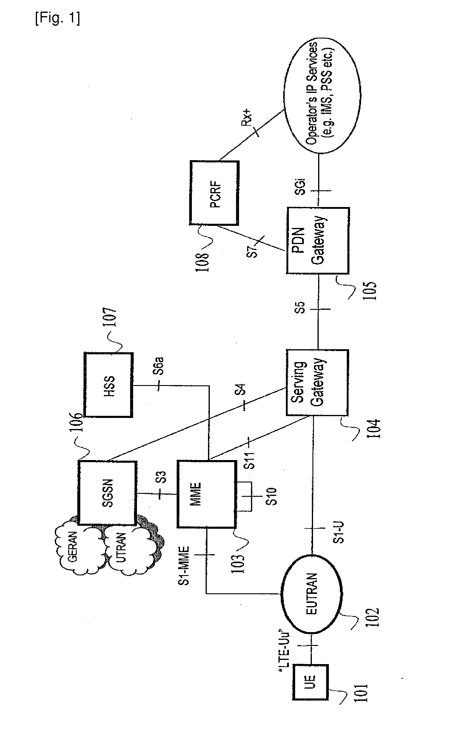
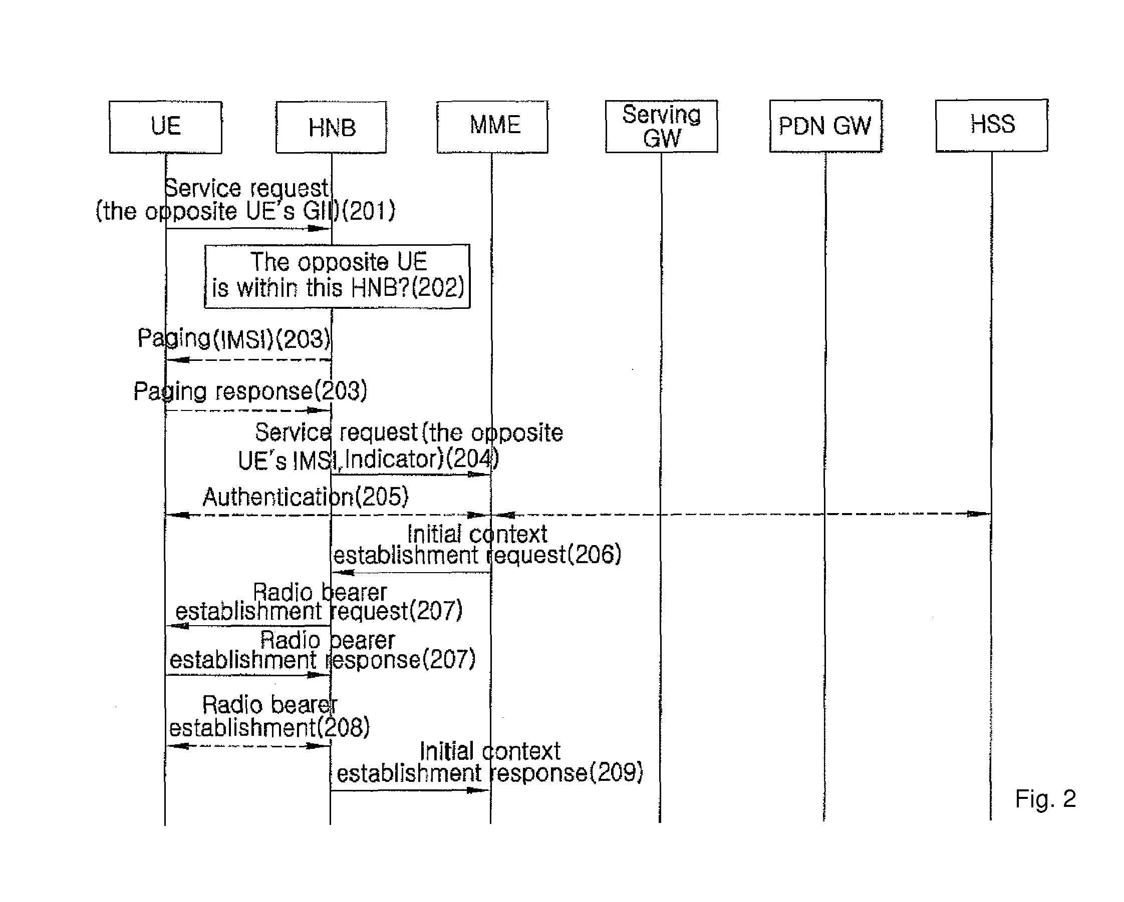
[0024 of the present invention is illustrated in FIG. 2. In this embodiment, the HNB access system can include HNB, or HNB and HNB GW. In the solution that the HNB access system includes the HNB and the HNB GW, the point where direct communication is implemented is the HNB. The HNB GW has the functions of forwarding messages between HNB and MME, taking charge of the mobility management of UEs within the control range of the HNB GW, etc.
[0025]The network (e.g., Operation Maintenance Center (OMC)) assigns an identifier GII, which is unique to a UE, to each of UEs within a CSG group. The identifier is saved in the corresponding UE. The International Mobile Subscriber Identifier (IMSI) and the GII of the UEs accessible in the group are saved in the HNB access system. Below is a detailed description to this figure. And detailed description on any technique irrelevant to the present invention is omitted.
[0026]Step 201, CSG UE (referred to as a first UE) under the HNB initiates a call to a...
embodiment 2
[0050 of the present invention is illustrated in FIG. 6. The network (e.g., Operation Maintenance Center (OMC)) assigns an identifier GII, which is unique to a UE, to each of UEs within a CSG group. The identifier is saved in the corresponding UE. The GII of the UEs accessible in the group are saved in the HNB access system. Below is a detailed description to this figure. And detailed description on any technique irrelevant to the present invention is omitted.
[0051]Step 601, a CSG UE in the HNB initiates a call to another UE in the same CSG. The UE sends a “service request” message to the HNB access system by way of an uplink information transfer message. The UE informs the HNB access system of the opposite-party UE's GII. The information element GII is optional. It is necessary only when the UE under an accessible HNB calls another UE in the same group. UE can send the GII to the HNB access system by way of either the uplink information transfer message or the service request messa...
embodiment 3
[0054 of the present invention is illustrated in FIG. 7. Direct communication is performed between UE1 and UE2 under the HNB access system. UE2 moves to a macro ENB. The corresponding signaling flow is illustrated in FIG. 8. Below is a detailed description on this figure. Here, detailed description on the techniques irrelevant to the present invention is omitted.
[0055]Step 801 the HNB access system sends a re-location request message to MME. According to context information, MME learns about that the UE1 is in the state of direct communication.
[0056]MME initiates the process of establishing a bearer for UE1, the process including steps 802 through 805. Here, the process of user plane bearer establishment of Serving GW-upstream nodes like PDN GW is omitted.
[0057]Step 802, MME sends a “bearer establishment request” message to the Serving GW. The Serving GW sends a “bearer establishment response” message to MME, the message including uplink TEID assigned by the Serving GW.
[0058]Step 80...
PUM
 Abstract
Description
Claims
Application Information
 - R&D
- Intellectual Property
- Life Sciences
- Materials
- Tech Scout
- Unparalleled Data Quality
- Higher Quality Content
- 60% Fewer Hallucinations
Browse by: Latest US Patents, China's latest patents, Technical Efficacy Thesaurus, Application Domain, Technology Topic, Popular Technical Reports.
© 2025 PatSnap. All rights reserved.Legal|Privacy policy|Modern Slavery Act Transparency Statement|Sitemap|About US| Contact US: help@patsnap.com