
Low profile ultrasound inspection scanner

a scanner and low-profile technology, applied in the direction of instruments, measurement devices, specific gravity measurements, etc., can solve the problems of inability to accurately inspect and the inability to accurately measure the structure of the boiler system

Active Publication Date: 2010-09-09
GENERAL ELECTRIC TECH GMBH +1
View PDF5 Cites 32 Cited by
  • Summary
  • Abstract
  • Description
  • Claims
  • Application Information

AI Technical Summary

Benefits of technology

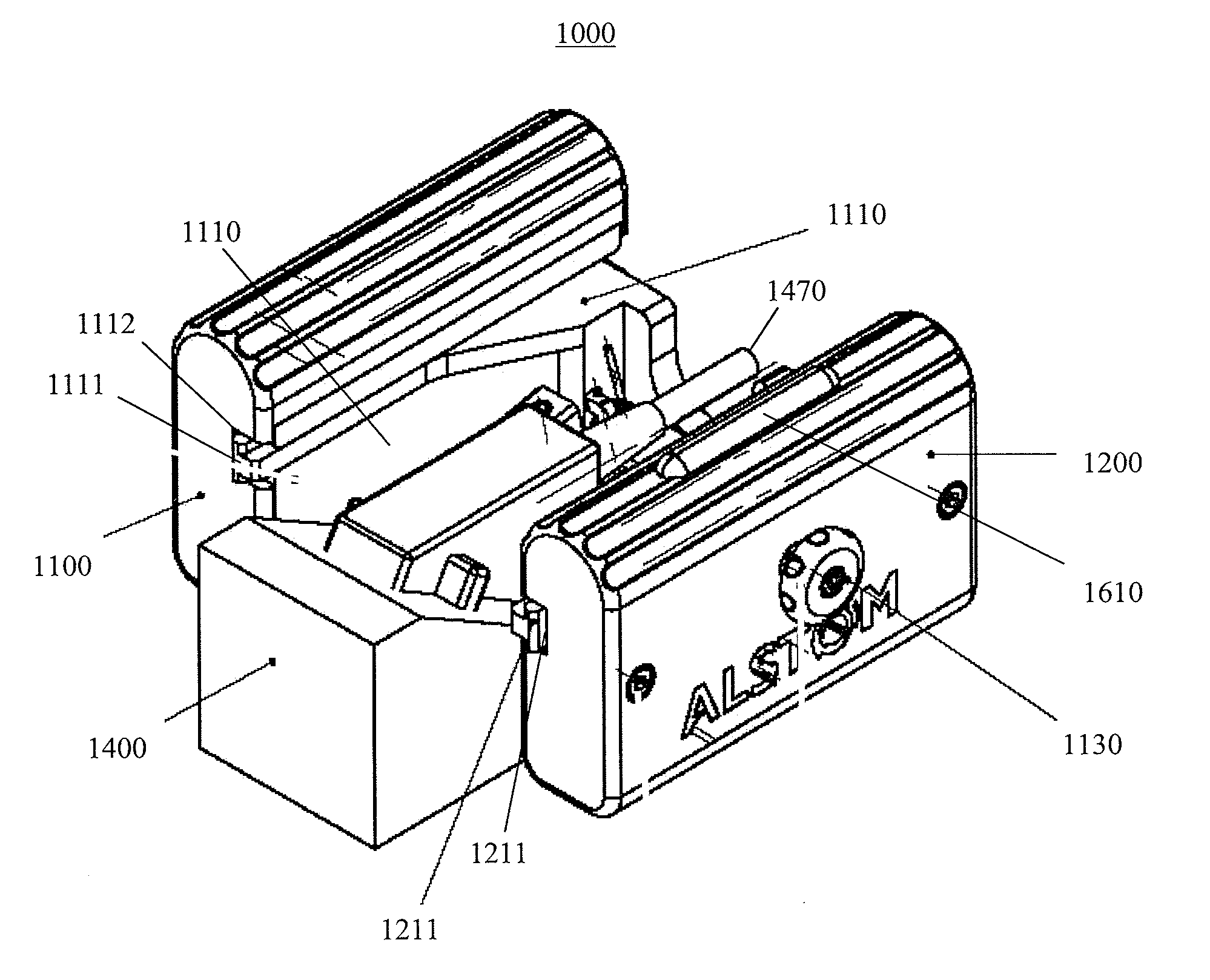
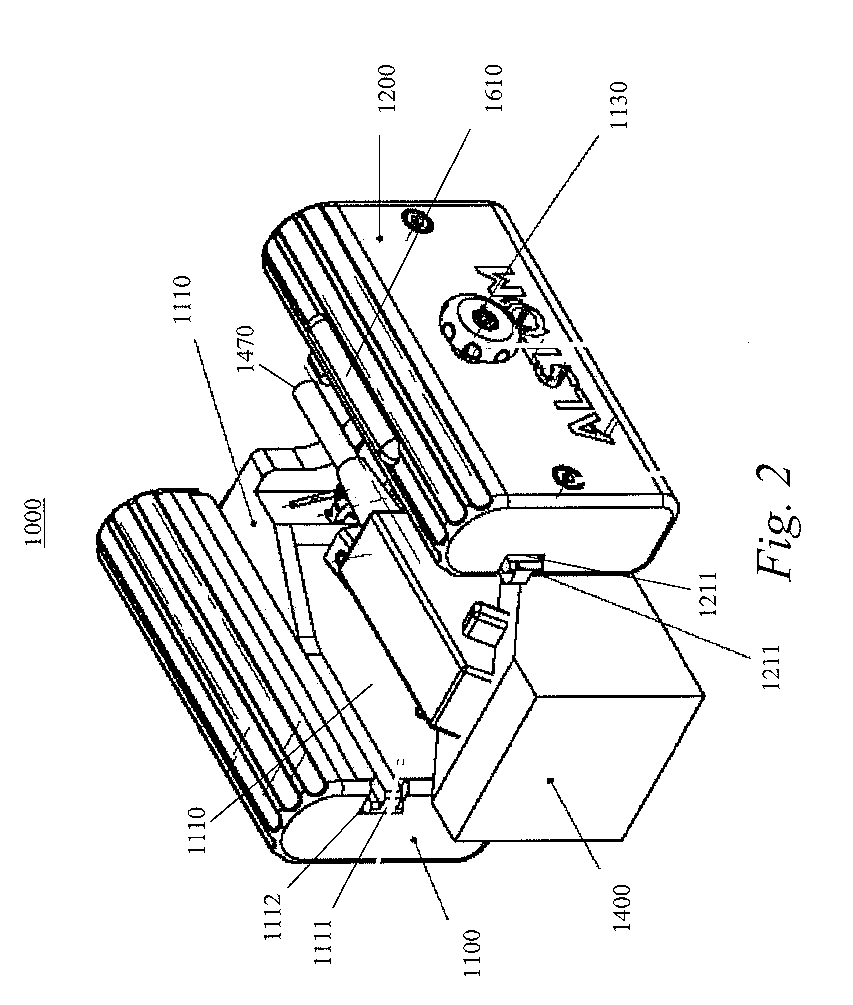
The ultrasonic probe carrier described in this patent is a specialized device for inspecting structures using ultrasound. It includes a lower profile inspection scanner, a wheel frame with attached ultrasound array, and wheels that can rotate to move the frame. The device can inspect various portions of a weld and is portable and designed for inspecting curved and flat surfaces. The device can also identify the location of ultrasound signals on the structure being inspected. Overall, this invention provides a more efficient and effective way to inspect power generation equipment.

Problems solved by technology

Testing of pressure parts and various structures using nondestructive testing techniques is an arduous task, particularly when testing seam welds.
For example, a boiler system having multiple components in a fixed, limited amount of space may be difficult to inspect with precision.
Clearly such a manual process is susceptible to inaccuracies, since a human operator's fine motor skills while traversing the structure, may not be entirely stable or consistent, which translates to less than optimal readings (e.g., missed cracks or wall degradation, false positives, and other such errors).
Since damage and failure typically begins at a weld seam of these components, it is important to inspect the welds periodically.
Due to their general-purpose nature, they tended to be large and bulky.
Due to the tight clearances, conventional inspection devices will not fit and are not adapted to the shape.

Method used


Image

  • Low profile ultrasound inspection scanner
  • Low profile ultrasound inspection scanner
  • Low profile ultrasound inspection scanner

Examples


Embodiment Construction

[0024]An ultrasonic inspection system (“system”) for providing nondestructive testing of pipe and piping welds having restricted or limited space therebetween is provided. The system includes an ultrasonic probe carrier having a low profile that enables the system to access tubes and welds having limited or restricted space among them.

[0025]Theory

[0026]Weaknesses in metal structures can be caused as a result of repeated mechanical forces acting on the structure, due to deterioration of from rust and corrosion, or due to improper initial construction. This applies especially to welds joints of metal structures, which ten to fail first.

[0027]These weaknesses may eventually cause a failure of a component. In the case of high-pressure components, failures may lead to catastrophic consequences.

[0028]Inspection and monitoring can identify these weaknesses before they can cause a problem. Once weakened components are identified, they may be replaced before there are safety issues and / or ad...


PUM

PropertyMeasurementUnit
heightaaaaaaaaaa
volumeaaaaaaaaaa
poweraaaaaaaaaa

Abstract

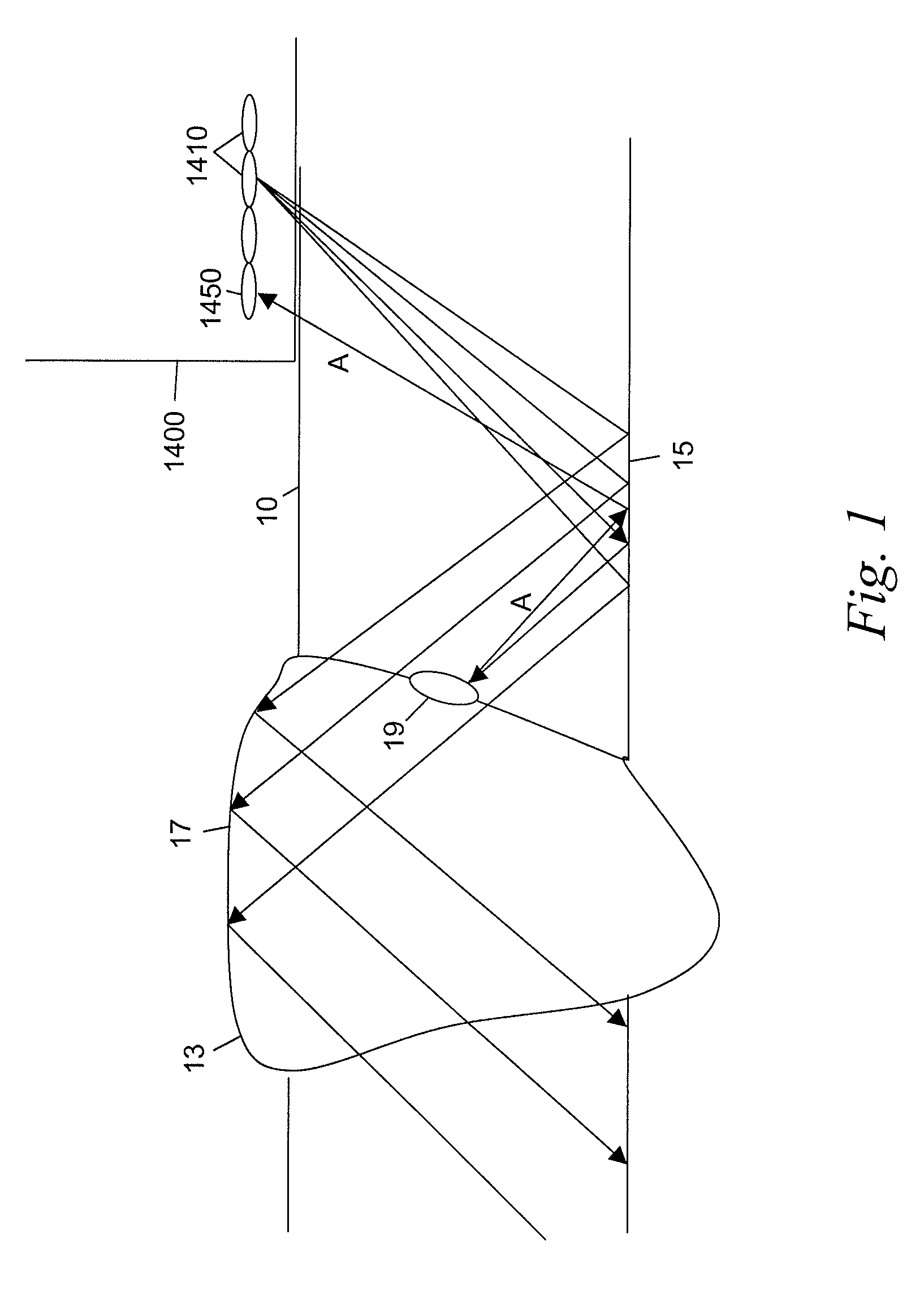
An inspection scanner [1000] is described that has a low profile construction designed to fit into tight spaces and inspect structures [10] such as weld joints [13]. Wheel frame assemblies [1100, 1200] carry a probe holder assembly [1110] with an ultrasonic (US) array [1400] that emits US beams through the structure [10] and receives reflected sound waves. The probe holder assembly [1110] extends and US beam is angled away to inspect in tight locations. The wheel frame assemblies [1100, 1200] roll on wheels [1140, 1240] that drive an encoder [1250]. Encoder [1250] provides the specific locations for the received sound waves with respect to the weld. The locations and received sound waves are used to reconstruct a signal showing imperfections inside of structure [10]. The wheels [1140, 1240] may be magnetic to hold it to the structure [10] being inspected. A brake system [1600] may be employed to hold the inspection scanner [1000] at a given location.

Description

TECHNICAL FIELD[0001]The present disclosure relates to a device for inspecting structures using ultrasound and more specifically, for a low profile device for inspecting structures using ultrasound in spaces with little clearance.BACKGROUND[0002]Testing of pressure parts and various structures using nondestructive testing techniques is an arduous task, particularly when testing seam welds. For example, a boiler system having multiple components in a fixed, limited amount of space may be difficult to inspect with precision. Typically, using ultrasonic techniques (UT), an operator manually scans the desired area of the structure with a hand-held UT probe that delivers signals (sound waves) through the structure and weld and receives feedback measurements as a result of the scanning. Clearly such a manual process is susceptible to inaccuracies, since a human operator's fine motor skills while traversing the structure, may not be entirely stable or consistent, which translates to less t...

Claims


Application Information

Patent Timeline
Patent Type & Authority Applications(United States)
IPC IPC(8): G01N29/04
CPCG01N29/07G01N29/225G01N29/262G01N29/265G01N2291/2693G01N2291/044G01N2291/106G01N2291/2675G01N2291/0289G01N29/22G01B17/04
Inventor BRIGNAC, JACQUES L.
Owner GENERAL ELECTRIC TECH GMBH
Learn More