Double Side Polishing Machine

a polishing machine and side polishing technology, which is applied in the direction of edge grinding machines, lapping machines, manufacturing tools, etc., can solve the problems of large variation of the upper lapping plate by the variability of the rod, and achieve the effect of preventing deflection of the upper polishing plate, reducing the variability of the upper lapping plate, and increasing the strength of the supporting pla

Inactive Publication Date: 2010-09-02
TSC CORP
View PDF5 Cites 3 Cited by
  • Summary
  • Abstract
  • Description
  • Claims
  • Application Information

AI Technical Summary

Benefits of technology

[0009]Thus, because the oscillation fulcrum of the upper lapping plate is located at approximately same height to the polishing surface thereof, distance between suspended positions of the upper polishing plate and the oscillation fulcrum can be made to a minimum, so that the variability of the upper polishing plate can be made to a minimum.
[0010]Besides, it is preferred that said upper polishing plate is suspended on the supporting plate outward in a radial direction from a center of gravity in one side of the polishing surface of the upper polishing plate. Thus, as the prior upper polishing plate is in a doughnut-shape, it has a tendency of warping so that the outer peripheral portion goes down, but because the upper polishing plate is supported outward from the center of polishing surface thereof, the outer peripheral portion thereof can be prevented going down and an inner peripheral portion thereof is difficult to go down, so that the deflection of the upper polishing plate can be prevented.
[0011]Furthermore, it is preferred that the supporting plate has a plurality of reinforcement ribs extending along the radiation direction. Thus, as strength of the supporting plate can be increased, the deflection of the upper lapping plate due to the deflection of the supporting plate can be prevented.
[0012]Moreover, it is preferred that the coupling mechanism is a gyro-mechanism and a center position of the gyro-mechanism is positioned at approximately same height to the polishing surface of the upper lapping plate. By this manner, load bias of the upper lapping plate due to a fine gap and an inclination of the supporting rod can be prevented.
[0013]Besides, it is preferred that the upper lapping plate can be rotatable by an upper lapping plate rotation mechanism for rotating the supporting rod and the upper lapping plate rotation mechanism is provided on the elevation mechanism. It has an effect such that a lower lapping plate rotation mechanism can be simplified by providing the upper lapping plate rotation mechanism separately from the lower lapping plate rotation mechanism. Thus, mechanical or structural resonance between the upper and the lower lapping plates can be prevented.
[0014]Due to the abovementioned constitution, according to the present invention, since an oscillation fulcrum of a coupling mechanism holding a support plate for upper lapping plate is positioned on an approximately same as a polishing surface of the upper lapping plate, distance between the polishing surface of the upper polishing plate and the oscillation fulcrum can be made to a minimum, so that an area of oscillation can be smaller and then polishing accuracy can be increased. Besides, positions suspending the upper polishing plate are positioned outward from a center of gravity in one side thereof and reinforcement ribs are formed on the supporting plate, so that deflection of the upper lapping plate can be prevented and load applied to works can be made uniformly and as a result, best accuracy double side polishing can be achieved.

Problems solved by technology

Besides, because a suspended position as an oscillation fulcrum of the upper lapping plate is at an end portion of the rod of the cylinder, distance between the upper lapping plate and the oscillation fulcrum is large and as a result, disadvantage such that variability of the upper lapping plate by variability of the rod is large is arisen.

Method used


Image

  • Double Side Polishing Machine
  • Double Side Polishing Machine
  • Double Side Polishing Machine

Examples


Embodiment Construction

[0018]Hereinafter, an embodiment of the present invention is explained by referring drawings.

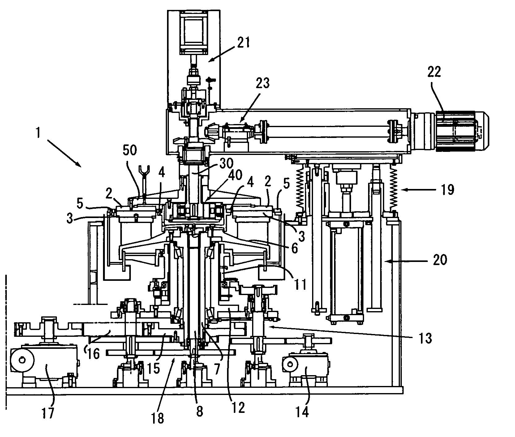
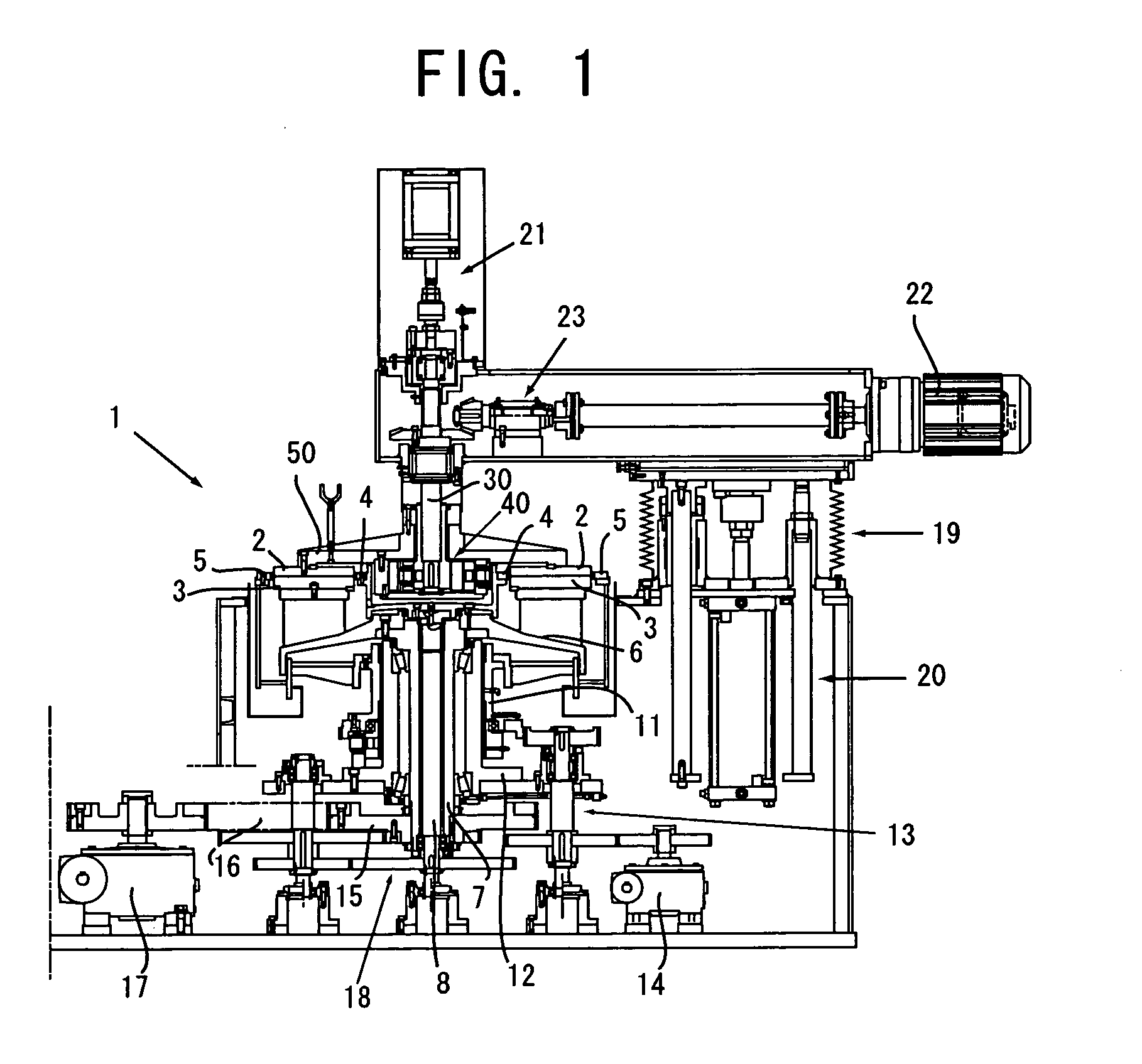
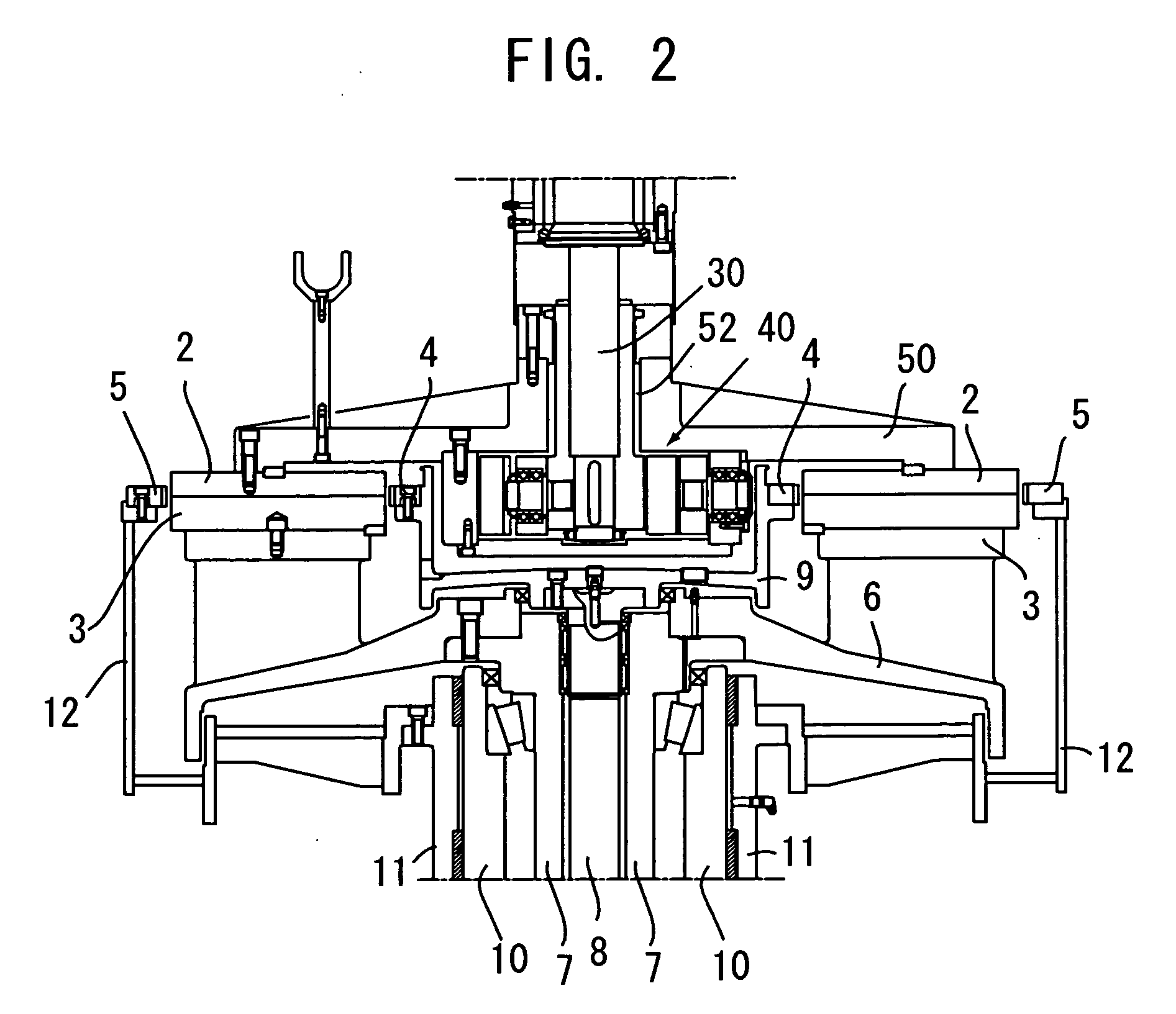
[0019]A double side polishing machine 1 according to an embodiment of the present invention comprises an upper polishing plate 2 and a lower polishing plate 3 between which a plurality of carriers not shown in figures installing plural works are put, and a sun gear 4 and an internal gear 5 with which the carriers are engaged in order to rotate and revolve.

[0020]The lower polishing plate 3 is secured on a supporting plate for lower polishing plate 6 to be held and rotated via a rotatable cylindrical shaft 7 on which the supporting plate 6 is secured. A rotation shaft 8 passing though the rotatable cylindrical shaft 7 is provided inside the rotatable cylindrical shaft 7, a closed-end and cylindrical sun gear portion 9 is secured at a front end of the rotation shaft 8, and then the sun gear 4 formed on an outer peripheral surface of the sun gear portion 9 is rotated with rotation of the rotatio...


PUM


Abstract

The present invention is to provide a double side polishing machine which can apply a load by the upper lapping plate uniformly to works and the deflection of the upper lapping plate is restrained, which comprises a rotatable lower lapping plate, a rotatable upper lapping plate and movable to the lower lapping plate by an elevation mechanism, carriers which are put between the lower lapping plate and the upper lapping plate and in which a plurality of works are mounted, and a rotation and revolution mechanism for rotating and revolving the carriers between the lower lapping plate and the upper lapping plate, wherein a supporting plate for upper lapping plate which suspends the upper lapping plate is connected to an upper portion of a coupling mechanism provided oscillatably on a vertically movable supporting rod of the elevation mechanism, and an oscillation fulcrum of the coupling mechanism is located at approximately same height to a polishing surface of the upper polishing plate.

Description

TECHNICAL FIELD[0001]This invention relates to a double side polishing machine for polishing a work such as a semiconductor wafer and a photomask.BACKGROUND ART[0002]A double side polishing machine disclosed in JP 2002-120143 A is that an upper lapping plate is supported by a cylinder for suspending in which fluid is a supporting medium so that a processing load can be applied uniformly to a work, namely that a plurality of supporting mechanisms supporting the upper lapping plate with fluid as supporting medium are provided at specific intervals around a center axis line of the upper lapping plate between a suspender for the lapping plate mounted on an elevator for rising and falling the upper lapping plate and the upper lapping plate.[0003]A polishing machine disclosed in JP 2002-154049 A is that a supporting disc whose size is similar to an upper lapping plate is provided on a front end of a rod of a cylinder device for elevating the upper lapping plate, and that deflection of the...

Claims


Application Information

Patent Timeline
Patent Type & Authority Applications(United States)
IPC IPC(8): B24B37/04B24B37/08
CPCB24B37/08
Inventor NAGASHIMA, TOSHIO
Owner TSC CORP
Why Eureka
Try Eureka