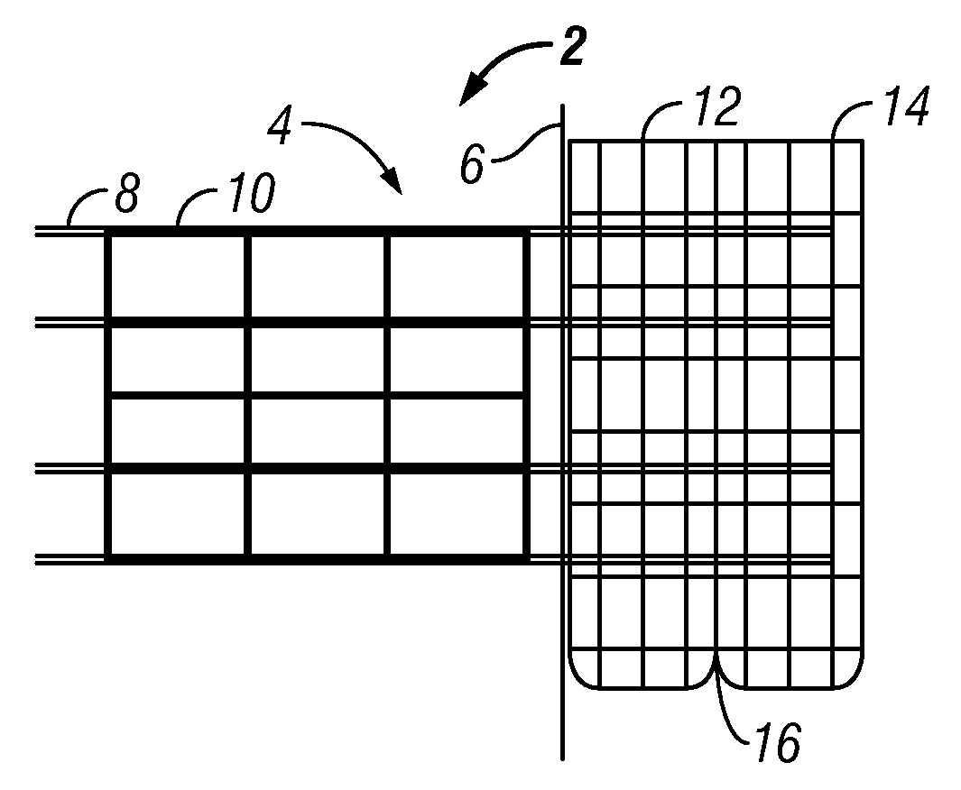
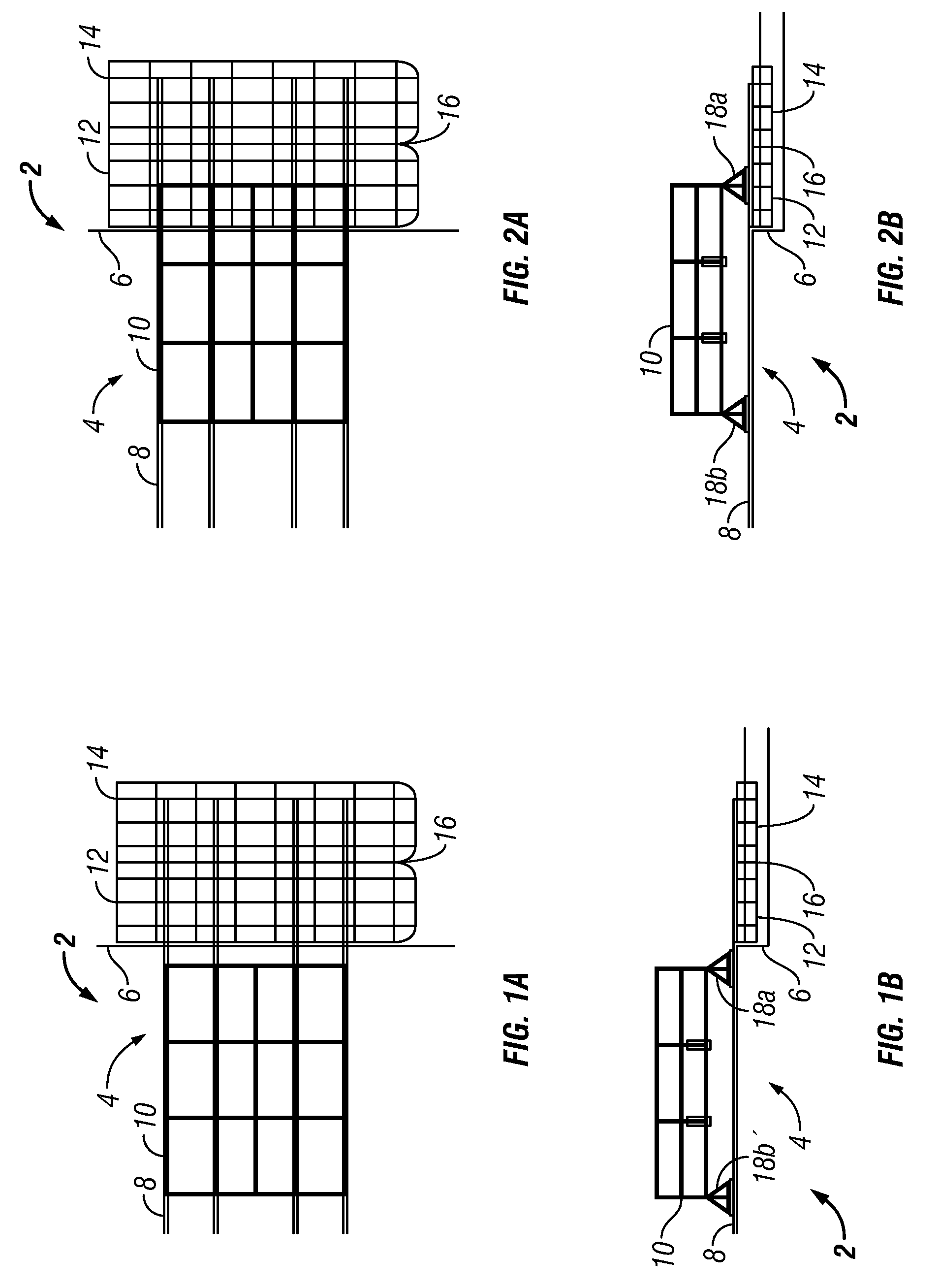
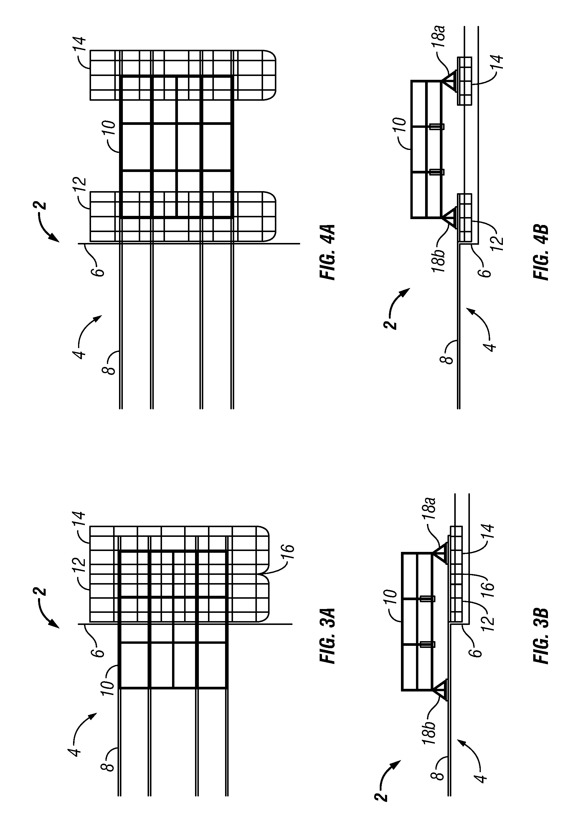
Topsides load-out to barge catamaran for float-over installation

a barge catamaran and topside technology, applied in special purpose vessels, caissons, constructions, etc., can solve the problems of increasing the cost and time of installing the topsides to the offshore structure, affecting the safety of the vessel, and the stern of the transportation barge generally lacks adequate strength, so as to achieve the effect of minimal racking

Inactive Publication Date: 2010-09-02
TECH FRANCE SA
View PDF5 Cites 5 Cited by
  • Summary
  • Abstract
  • Description
  • Claims
  • Application Information

AI Technical Summary

Benefits of technology

[0013]The present invention provides an improved method and system for load-out of a topsides onto at least two float-out barges without requiring an intermediate transportation barge. The topsides and float-over barges creates a catamaran system that can be used to install the topsides to an offshore structure, such as a Spar hull, using a float-over method. The load-out process offers several advantages and can be less time-consuming and less expensive than a typical procedure using the intermediate transportation barge.
[0015]the skid rails on the float-over barges can be part of the barge grillage structure for the catamaran system, thus saving a significant amount of steel compared with a load-out in the traditional direction along the length of the transportation barge;
[0019]the topsides can experience minimal racking between the two barges resulting from a more uniform distribution of the topsides loads on the supports during the load-out operation to the float-over barges.
[0021]In at least one embodiment, the method includes: positioning a first float-over barge in proximity to the loading structure and restraining movement of the first float-over barge relative to the loading structure; coupling a second float-over barge to the first float-over barge distally from the loading structure; loading out the portion of the topsides onto the first float-over barge; loading out the portion of the topsides off of the first float-over barge and onto the second float-over barge; decoupling the second float-over barge from the first float-over barge; and loading out the remainder of the topsides onto the first float-over barge and allowing the second float-over barge to be separated by a distance from the first float-over barge.
[0022]In another embodiment, the method includes: positioning a first float-over barge in proximity to the loading structure and restraining movement of the first float-over barge relative to the loading structure; loading out the portion of the topsides onto the first float-over barge; allowing the first float-over barge to be moved relative to the loading structure; loading out the topsides toward the first float-over barge and allowing the first float-over barge to be separated by a distance from the loading structure; positioning a second float-over barge in proximity to the loading structure and restraining movement of the second float-over barge relative to the loading structure; and loading out the remainder of the topsides from the loading structure onto the second float-over barge separated from the first float-over barge.

Problems solved by technology

Deck or topsides installation has always been a challenge for floating structures, particularly in deep draft floaters like the Spar, which must be installed in relatively deep water.
There are some disadvantages in a lifted installation, particularly for large topsides requiring multiple module lifts.
Such multi-lift increases the costs and time for installing the topsides to the offshore structure.
These operations are time consuming, because they require transfer of the topsides from the quay to the transportation barge and after loading the topsides to the transportation barge, then to the two barges.
A further challenge is that the stern of the transportation barge generally lacks adequate strength for the reaction load from the topsides during the load-out at the yard and requires special care and procedures to accommodate the load-out.
This challenge is partially due to the practice of aligning the narrower transverse dimension (that is, width) of the transportation barge against the dock with the longer longitudinal dimension (that is, length) extending away from the dock.
This relatively narrow width further complicates the loading by resulting in limiting the ballast available at any given width of the transportation barge.

Method used


Image

  • Topsides load-out to barge catamaran for float-over installation
  • Topsides load-out to barge catamaran for float-over installation
  • Topsides load-out to barge catamaran for float-over installation

Examples


Embodiment Construction

[0039]The Figures described above and the written description of specific structures and functions below are not presented to limit the scope of what Applicants have invented or the scope of the appended claims. Rather, the Figures and written description are provided to teach any person skilled in the art to make and use the inventions for which patent protection is sought. Those skilled in the art will appreciate that not all features of a commercial embodiment of the inventions are described or shown for the sake of clarity and understanding. Persons of skill in this art will also appreciate that the development of an actual commercial embodiment incorporating aspects of the present inventions will require numerous implementation-specific decisions to achieve the developer's ultimate goal for the commercial embodiment. Such implementation-specific decisions may include, and likely are not limited to, compliance with system-related, business-related, government-related and other c...


PUM


Abstract

The present invention provides an improved method and system for load-out of a topsides onto at least two float-over barges without requiring an intermediate transportation barge. The topsides and float-over barges create a catamaran system that can be used to install the topsides to an offshore structure, such as a Spar hull, using a float-over method. The load-out process offers several advantages and can be less time-consuming and less expensive than a typical procedure using the intermediate transportation barge.

Description

CROSS REFERENCE TO RELATED APPLICATIONS[0001]Not applicable.STATEMENT REGARDING FEDERALLY SPONSORED RESEARCH OR DEVELOPMENT[0002]Not applicable.REFERENCE TO APPENDIX[0003]Not applicable.BACKGROUND OF THE INVENTION[0004]1. Field of the Invention[0005]This invention relates a method and system of loading out an integrated floating platform topsides from a fabrication or ship yard to a catamaran setup made of two barges for ocean towing and ultimately for a float-over installation onto an offshore structure such as a Spar.[0006]2. Description of the Related Art[0007]Many offshore structures require a topsides to provide support facilities to operate the offshore structures for their intended purpose. For example, a Spar platform is a type of floating oil platform typically used in very deep waters and is among the largest offshore platforms in use. A Spar platform includes a large cylinder or hull supporting a typical rig topsides. The cylinder however does not extend all the way to th...

Claims


Application Information

Patent Timeline
IPC IPC(8): E02D25/00
CPCB63B35/003B63B9/065B63B77/00
Inventor LUO, MICHAEL Y.H.EDELSON, DAVIDCHEN, LIYONG
Owner TECH FRANCE SA
Why Eureka
Try Eureka