[0049]As disclosed in PCT / US08 / 58824, the ITCS is able to detect so called pseudo emitters and use multi-path
ambiguity resolution algorithms to reduce or eliminate positional
ambiguity these signals introduce when attempting to identify the locations of RFID tagged items in a target area. While the prior ITCS RFID tracking and
location systems included extensive logic dedicated to the identification and rejection of these pseudo emitter signals, the present invention recognizes that these signals, especially when their appearance, location and / or disappearance is tracked over time as part of the overall RF environment fingerprint present in a target area, may be interpreted as an object presence and / or location indicator for untagged objects within the target area.
[0051]The rules engine 5 compares the real time RF environment fingerprint with a set of baseline calibration RF environment fingerprint data sets to identify pseudo emitter and / or response
signal degradation indications of changes to the number and / or position of untagged objects present in the target area. Resolution of the location, pseudo emitter and / or response
signal degradation indications is greatly increased when
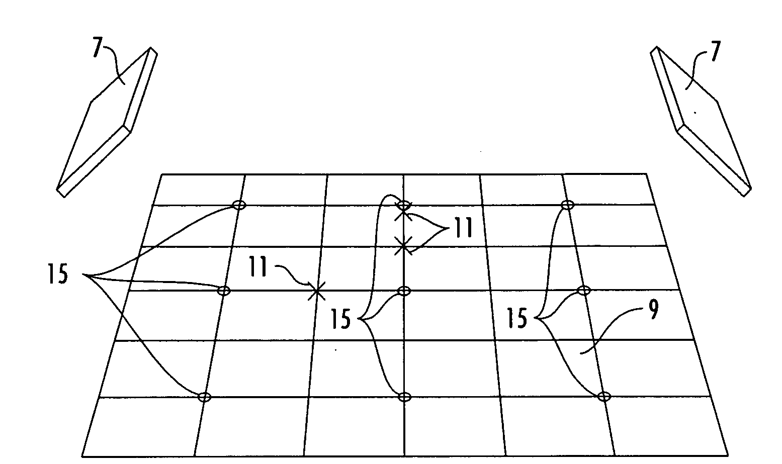
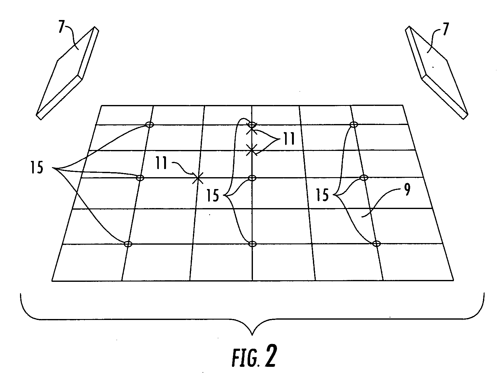
multiple antenna(s) 7 of the ITCS are arrayed about the target area 9, for example as shown in FIG. 2. At least two antenna(s) 7 enabling the application of
triangulation logic between a beam vector of each antenna 7 to generate an accurate z-axis position parameter of
signal sources useful alone or as a further accuracy check upon z-axis estimates derived from
signal timing routines.
[0052]The rules engine 3 operates upon two primary indications of an untagged object(s) 11 presence in the target area 9, demonstrated in FIGS. 3-5. First, in a
line of sight parameter 13, the response signal from a reference RFID tag 15, will become measurably degraded and / or
cut off entirely as untagged object(s) 11 and / or structures 17 occur in and / or are placed in the signal path between the reference RFID tag 15 and an antenna 7, for example covering and / or obscuring the signal path to a reference RFID tag 15, thereby identifying the presence of an untagged object 11 along a signal path between the reference RFID tag 15 and an antenna 7. The reference RFID tag(s) 15 may be passive RFID tags permanently attached around the target area 9, for example on the floors, shelving and / or ceiling of a storeroom, warehouse or other space to be monitored. Second, in a pseudo emitter parameter 19, untagged objects and / or structures 17 including RF
reflective surfaces (
metal and / or
metal coated surfaces) occurring and / or placed
proximate a reference RFID tag 15 signal path will generate pseudo emitter responses with respect to that RFID tag 15 that may be located in three dimensions within the target area 9 as if they were RFID tags, themselves. Further, where separate antenna(s) 7 are arrayed about the target area 9, the different lines of
sight between each antenna 7, various reference RFID tag(s) 15 and an untagged object 11 may generate both
line of sight signal parameter 13 and pseudo emitter parameter 19 responses with respect to the same untagged object(s) 11, greatly improving the rules engine accuracy (for diagram
clarity, representative signal paths / parameters are diagrammed with respect to only one of the antenna 7).
[0066]To improve
signal quality, the
background noise signature may be subtracted from any of the other signatures, such as the instantaneous signature, the average signature and the running reference signature, a procedure referred to as
noise canceling.
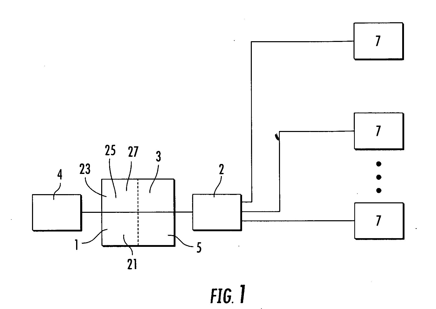
[0074]The primary signature (sig prime) is then compared with the reference signature from the
data matrix 5 in a further
comparator processor 27. If there is a significant change, then the resulting nature of the change is routed to the rules engine 3, which triggers the appropriate action according to the established rules framework. If there is no significant change, then it is assumed that the environment has remained stable over the preceding period of time. The method using two antenna systems is the same. However because there are two steerable beam base stations, it is possible to more accurately determine a point in space using the
azimuth and elevation positions from the two base stations to derive X, Y and Z positional information via
triangulation. Further, dual (or more) signal beams intersecting at a desired location increase the interrogation
signal intensity, for the desired point of interest, without radiating RF power beyond established limits, outside of the target area 9.


