
Devices and Methods for Lift Assistance

a technology of lifting assistance and devices, applied in the field of lifting techniques, can solve the problems of temporary difficulty after surgery, elderly, disabled, pregnant or the weak may have considerable difficulty standing or sitting, and the routine movement of most people is not so routine for certain classes of peopl

Inactive Publication Date: 2010-09-02
ELEVATORSEAT CORP
View PDF14 Cites 47 Cited by
  • Summary
  • Abstract
  • Description
  • Claims
  • Application Information

AI Technical Summary

Benefits of technology

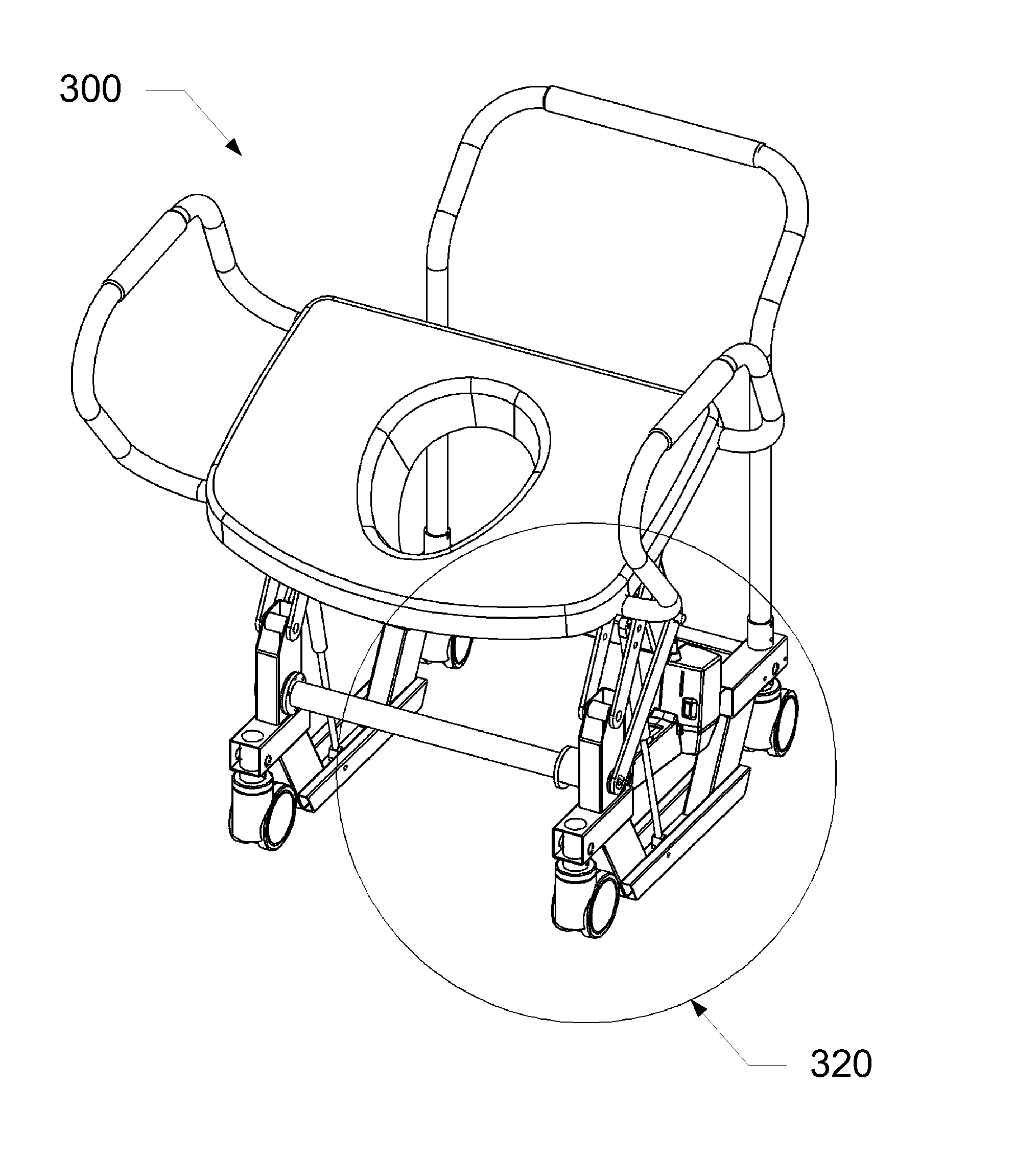
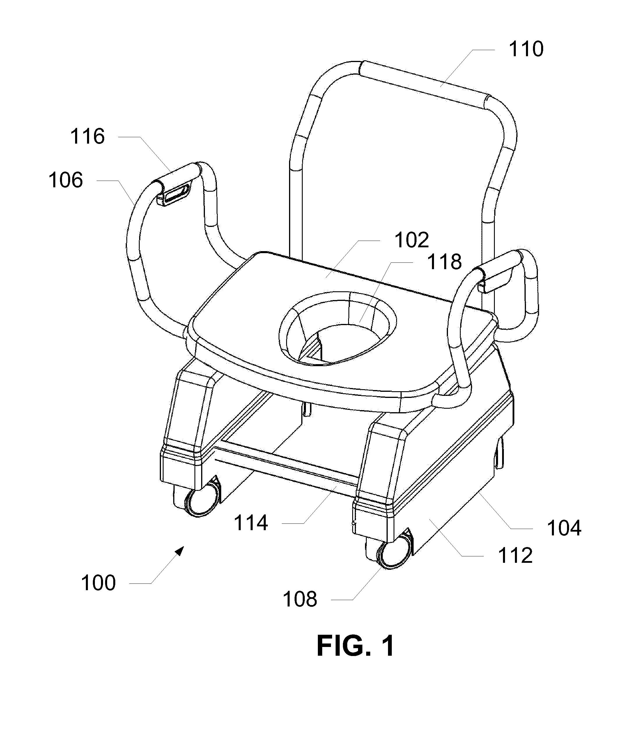
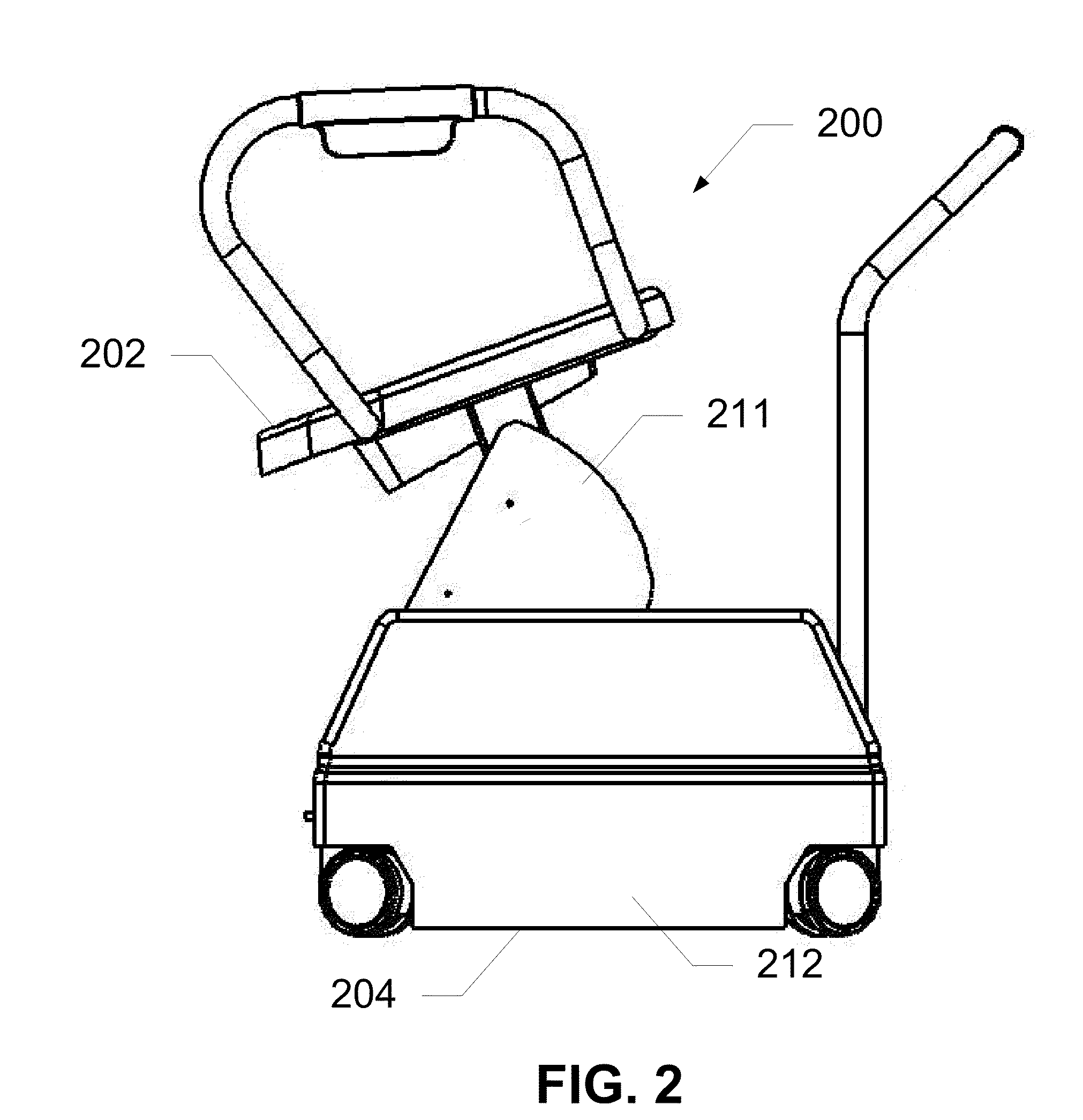
[0010]The present invention solves the above problems by incorporating a lifting mechanism into a seat coupled to a movable base portion. As the lifting portion lifts the seat, an angle of the seat changes from a substantially horizontal position to a relatively angled position, mimicking the natural motion of the hips and thighs for humans needing assistance. Actuators coupled to drive shafts enable a plurality of linkages to be raised and tilted, enabling the seat to rise at the push of a button or other triggering mechanism. A plurality of compressible springs enables an even balance between the weight of the human and the pressure of the lifting mechanism underneath the seat. The device can be used as a bedside toilet, having a removable bowl attached to the seat, or placed over a toilet, and can accordingly be height-adjusted to fit most existing toilets.
[0013]In yet another exemplary embodiment, the present invention is method for lifting a user from a substantially sitting position to a substantially standing position, the method including positioning the user in a substantially sitting position on a device having a planar seat portion, a lifting mechanism, and a base portion, mechanically driving the seat portion substantially upward at a comfortable pace, supporting the seat portion evenly via a plurality of extendible springs pivotally coupled to the base portion and the seat portion, maintaining, dynamically, the seat portion at a critical angle to provide even support to a weight of the user and a leaning force of the user as the seat is driven upward until the user reaches a substantially standing position, and mechanically lowering the seat portion following the critical angle until the user reaches a substantially sitting position. The maintaining step further comprises a first, lowered angle that is substantially planar and a second, lifted angle that is substantially horizontal, so as to counteract a leaning force of a user. The device may be placed over a toilet seat. A handlebar can be removed to enable a user to be transported from the device onto a bed and vice versa.

Problems solved by technology

However, such movements, which are routine for most people, are not so routine for certain classes of people.
For example, the elderly, the disabled, the obese, the pregnant, or the weak may have considerable difficulty standing or sitting.
Other persons who typically have no problem with the movement of sitting or standing could also have temporary difficulty after surgery or injury.
Thus, there are many situations where persons will have temporary or permanent difficulty with the routine process of sitting or standing.
However, a major drawback of using standard crutches is the need for considerable upper body strength to support a substantial portion of the body weight during the process of sitting or standing.
Also, crutches tend to move with the shift of weight, and can often slip at the most crucial time, when the person using them is supporting all of his or her weight on the crutches.
Such movement can result in injury to the person using these crutches.
Thus, there is still some risk of injury to the person using the walker during such motion.
However, these devices are typically not designed specifically for a toilet seat and have a one way axis of motion, resulting in a sudden jerk movement that could potentially cause harm or injury to an already weakened, fragile, or injured body, as well as require additional vertical motion which a user may not have the strength to provide.

Method used


Image

  • Devices and Methods for Lift Assistance
  • Devices and Methods for Lift Assistance
  • Devices and Methods for Lift Assistance

Examples


Embodiment Construction

[0032]The present invention presents a novel technique for lifting users from a seated position to a substantially standing position without suffering from some of the drawbacks of conventional devices. A lifting mechanism is coupled between a seat portion and a movable base portion. The lifting mechanism includes a pair of upper and lower linkages pivotally coupled to different points on vertical supports on the base portion and on seat supports on the seat portion. An actuator provides rotational energy to a drive shaft that is fixedly coupled to a front end of at least one of the linkages. As the drive shaft rotates, the linkages move in such a way so as to lift the seat while changing an angle of the seat from a substantially horizontal position (seated) to a relatively angled position (raised). A plurality of compressible springs enables an even balance between the weight of the human and the pressure of the lifting mechanism underneath the seat. Furthermore, the device also in...


PUM


Abstract

Devices and methods are disclosed which relate to lifting a user from a seated position to a raised position. This is performed by incorporating a lifting mechanism into a seat coupled to a movable base portion. Actuators coupled to drive shafts enable a plurality of linkages to be raised and tilted, enabling the seat to rise at the push of a button or other triggering mechanism. A plurality of compressible springs enables an even balance between the weight of the human and the pressure of the lifting mechanism underneath the seat. As the lifting portion lifts the seat, an angle of the seat changes from a substantially horizontal position to a relatively angled position, mimicking the natural motion of the hips and thighs for humans needing assistance. Embodiments disclosed include using the device as a bedside toilet, having a removable bowl attached to the seat, or using the device placed over a toilet.

Description

[0001]This U.S. Utility Patent Application claims priority to U.S. Provisional Patent Application Ser. No. 61 / 180,733, filed May 22, 2009; and is a continuation-in-part (CIP) of U.S. patent application Ser. No. 11 / 747,160, filed May 10, 2007; which claims priority to U.S. Provisional Patent Application Ser. No. 60 / 799,660, filed May 12, 2006; and to U.S. Provisional Patent Application Ser. No. 60 / 831,217, filed Jul. 17, 2006, the contents of all of which are hereby incorporated by reference in their entirety into this disclosure.BACKGROUND OF THE INVENTION[0002]1. Field of the Invention[0003]The present invention relates to techniques for lifting. In particular, the present invention relates to devices and methods for lifting humans from a seated position to a raised position and vice versa.[0004]2. Background of the Invention[0005]The process of sitting or standing is one of the most common and routine movements for human beings. The human body is designed to be able to perform suc...

Claims


Application Information

Patent Timeline
IPC IPC(8): A47C1/00A61G5/14A47K11/04
CPCA61G5/14A61G7/1007A61G2200/36A61G2200/34A61G7/1046
Inventor NELSON, JEFFREY C.KILGORE, GREGORY C.
Owner ELEVATORSEAT CORP
Learn More