
Method for molding optical member, apparatus for molding optical member and optical member

a technology of optical components and molding methods, applied in the direction of dough shaping, manufacturing tools, instruments, etc., can solve the problems of difficult injection molding, poor flowability of nanocomposite resin, failure to obtain transparent optical components with constant dispersion density, etc., and achieve stable optical characteristics

Inactive Publication Date: 2010-08-26
FUJIFILM CORP
View PDF2 Cites 7 Cited by
  • Summary
  • Abstract
  • Description
  • Claims
  • Application Information

AI Technical Summary

Benefits of technology

The present invention provides an optical member molding method and apparatus that can mold a light-transparent optical member from a nanocomposite resin that includes a thermoplastic resin containing inorganic fine particles. This method and apparatus can allow for the stable formation of optical members with uniform optical characteristics and high refractive indices. The method involves charging a solution containing the nanocomposite resin into a vessel and evaporating the solvent to solidify the solution and form the optical member in a finished shape. The resulting optical member has stable optical characteristics and can be easily molded in a short time as compared to molding two optical members separately. The method and apparatus can also allow for the molding of optical members with complex shapes. The solution is charged under reduced pressure to ensure full spreading in the vessel and the absence of bubbles during the molding process. The technical effects of this invention include the ability to mold high-quality optical members from nanocomposite resin and the improvement of optical properties through the uniform dispersion of inorganic fine particles.

Problems solved by technology

In the method (1), the nanocomposite resin exhibits bad flowability even at a high temperature and not only injection molding is difficult but also fine particles are locally aggregated, failing in obtaining a transparent optical member with a constant dispersion density.
Also, since high quality is required of the optical member, the material remaining in the runner at injection molding is not reused but discarded due to quality deterioration, and this leads to an about 90% loss of the material based on the entire charged amount and a rise in the cost of a high value-added material such as nanocomposite resin.
In the method (2), distortion remains and affects the optical characteristics.
However, this method is disadvantageous in that, for example, light is reflected on an interface generated inside of the optical member and optical axis displacement readily occurs.

Method used


Image

  • Method for molding optical member, apparatus for molding optical member and optical member
  • Method for molding optical member, apparatus for molding optical member and optical member
  • Method for molding optical member, apparatus for molding optical member and optical member

Examples


Embodiment Construction

[0039]Exemplary embodiments of the method and apparatus for molding an optical member of the present invention are described in detail below by referring to the drawings.

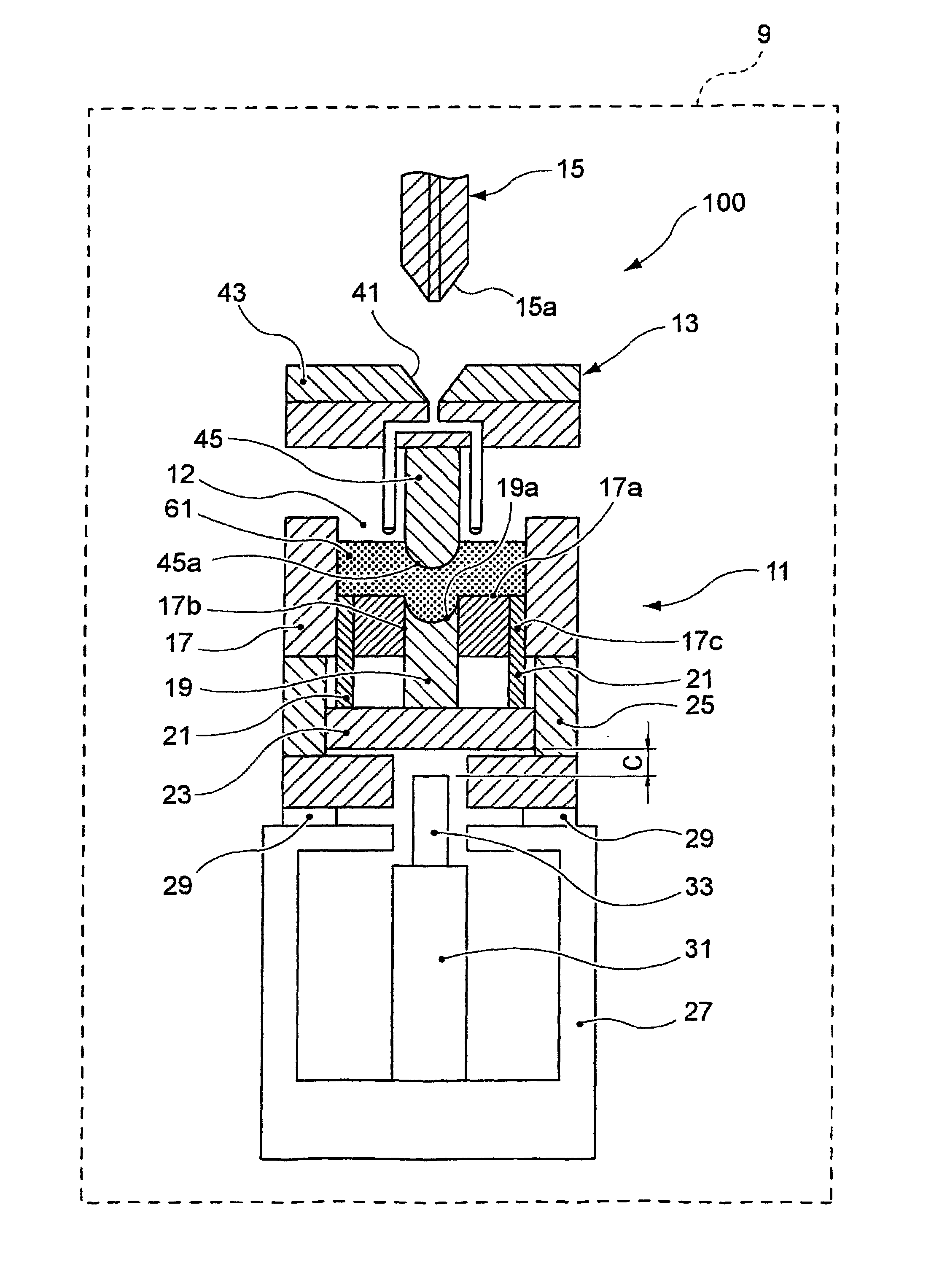
[0040]FIG. 1 is a longitudinal cross-sectional view showing a rough construction of an optical member molding apparatus according to an exemplary embodiment of the present invention, and FIG. 2 is an explanatory view schematically showing steps through which an optical member is molded from a nanocomposite resin-containing solution by the optical member molding apparatus shown in FIG. 1.

[0041]As shown in FIG. 1, the optical member molding apparatus 100 includes a vessel-like lower mold 11, a convex upper mold 13 and a dispenser device 15 and is arranged in a drying chamber 9. The vessel-like lower mold 11 includes an approximate cylindrical vessel 17 open to the outside at an open-to-atmosphere surface (an opening to an atmosphere) 12 provided on the top, a core 19 capable of slidably fitting into a core hole 17b pr...


PUM

PropertyMeasurementUnit
particle sizeaaaaaaaaaa
temperatureaaaaaaaaaa
diameteraaaaaaaaaa

Abstract

A method for molding an optical member from a material of a nanocomposite resin which includes a thermoplastic resin containing inorganic fine particles is provided. The method includes: charging a solution containing a solvent and the nanocomposite resin into a vessel providing at least an optical surface shape and an opening to an atmosphere, and evaporating the solvent from the opening to solidify and form an optical surface of the optical member into a finished shape.

Description

TECHNICAL FIELD[0001]The present invention relates to an optical member molding method, an optical member molding apparatus and an optical member. More specifically, the present invention relates to an optical member molding method and an optical member molding apparatus, where an optical member with excellent optical characteristics can be formed using a nanocomposite resin, and an optical member.BACKGROUND ART[0002]With recent progress of high-performance, compact and low-cost portable cameras and optical information recording devices such as DVD, CD or MO drive, development of excellent materials and processes is strongly demanded also for optical members such as optical lens and filter used in these recording devices.[0003]A plastic lens is lightweight and hardly broken as compared with an inorganic material such as glass, can be processed into various shapes and has an advantage over a glass-made lens in view of cost and therefore, its usage is rapidly spreading not only as a s...

Claims


Application Information

Patent Timeline
Patent Type & Authority Applications(United States)
IPC IPC(8): G02B3/00B29D11/00
CPCB29C39/003B29C39/26B29C39/42B29D11/00009G02B1/041B29L2011/0016C08L43/02B29D11/00346B29D11/00442
Inventor YOSHIOKA, MASATOEIHA, NORIKOWATANABE, SEIICHI
Owner FUJIFILM CORP
Learn More