
Soft ablative desorption method and system

a soft ablative and sample technology, applied in the field of mass spectrometry sample preparation methods, can solve the problem of rapid ablation of samples within the irradiated zone, and achieve the effect of improving reproducibility and lowering detection limits

Active Publication Date: 2010-08-26
LIGHT MATTER INTERACTION INC
View PDF5 Cites 37 Cited by
  • Summary
  • Abstract
  • Description
  • Claims
  • Application Information

AI Technical Summary

Benefits of technology

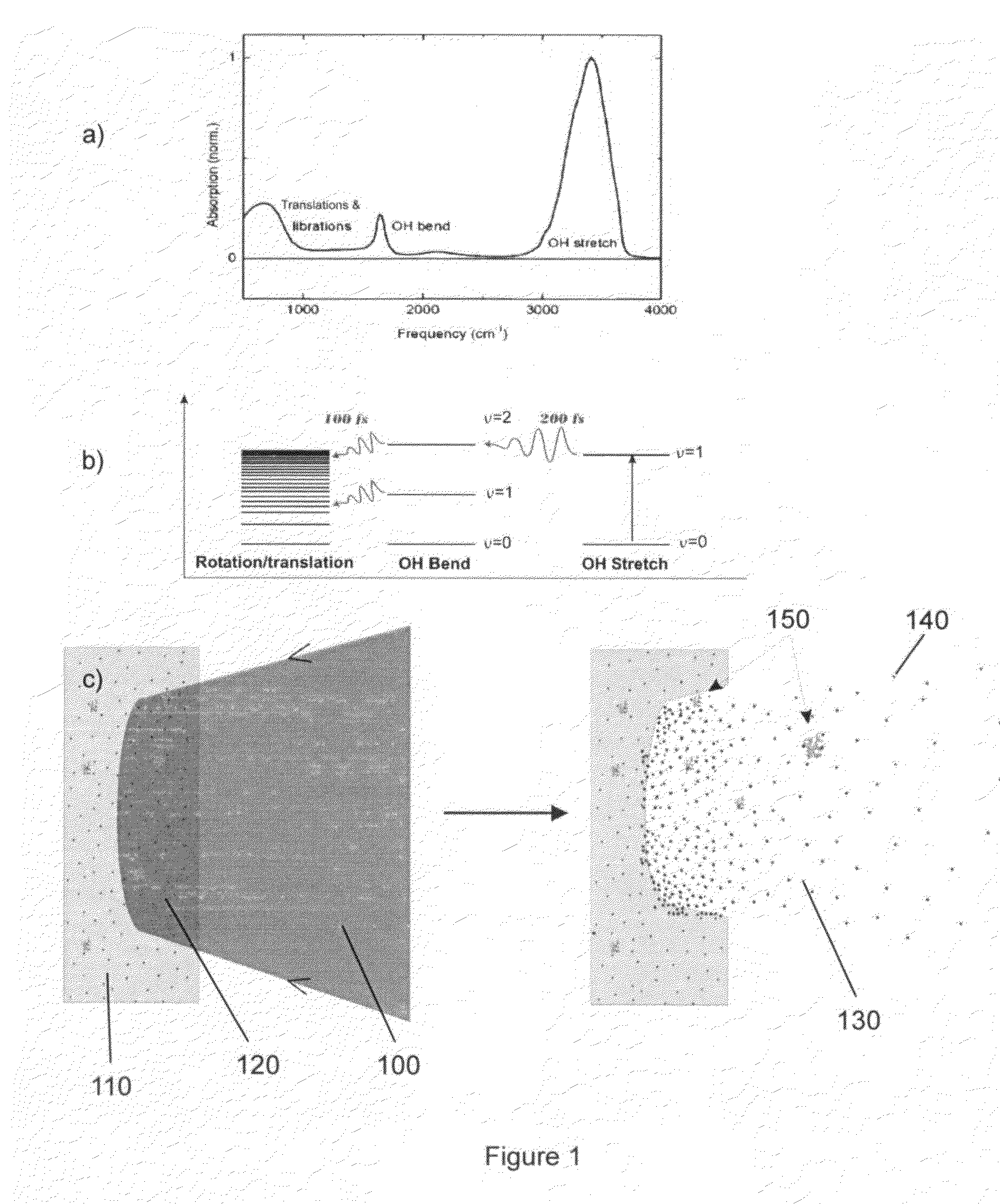
"The present invention provides methods and systems for improving the reproducibility and detection limit of sample desorption and mass spectrometry sample preparation. The methods involve using an optical beam to soft desorb analyte from a sample by exciting vibrational levels of a component of the sample. The optical beam is absorbed by the component, causing it to quickly transfer energy to translational motion. The energy is then rapidly lost through thermal diffusion and acoustic expansion, resulting in the analyte being desorbed without ionization and fragmentation. The desorbed analyte is then ionized and directed towards the inlet of a mass analysis device. The systems include an optical apparatus for directing the optical beam onto the sample and an ionization means for ionizing the desorbed analyte. The technical effects of the invention include improved reproducibility, reduced detection limit, and improved soft desorption of analyte from samples."

Problems solved by technology

As a result, the energy deposited by the optical beam is primary provided to translational motion through the above process, resulting in the rapid ablation of the sample within the irradiated zone.

Method used


Image

  • Soft ablative desorption method and system
  • Soft ablative desorption method and system
  • Soft ablative desorption method and system

Examples


Embodiment Construction

[0055]Without limitation, the majority of the systems described herein are directed to a process involving the soft ablative desorption of an analyte. As required, embodiments of the present invention are disclosed herein. However, the disclosed embodiments are merely exemplary, and it should be understood that the invention may be embodied in many various and alternative forms.

[0056]The Figures are not to scale and some features may be exaggerated or minimized to show details of particular elements while related elements may have been eliminated to prevent obscuring novel aspects. Therefore, specific structural and functional details disclosed herein are not to be interpreted as limiting but merely as a basis for the claims and as a representative basis for teaching one skilled in the art to variously employ the present invention. For purposes of teaching and not limitation, the illustrated embodiments are directed to the soft ablative desorption of an analyte, in particular when t...


PUM

PropertyMeasurementUnit
time intervalaaaaaaaaaa

Abstract

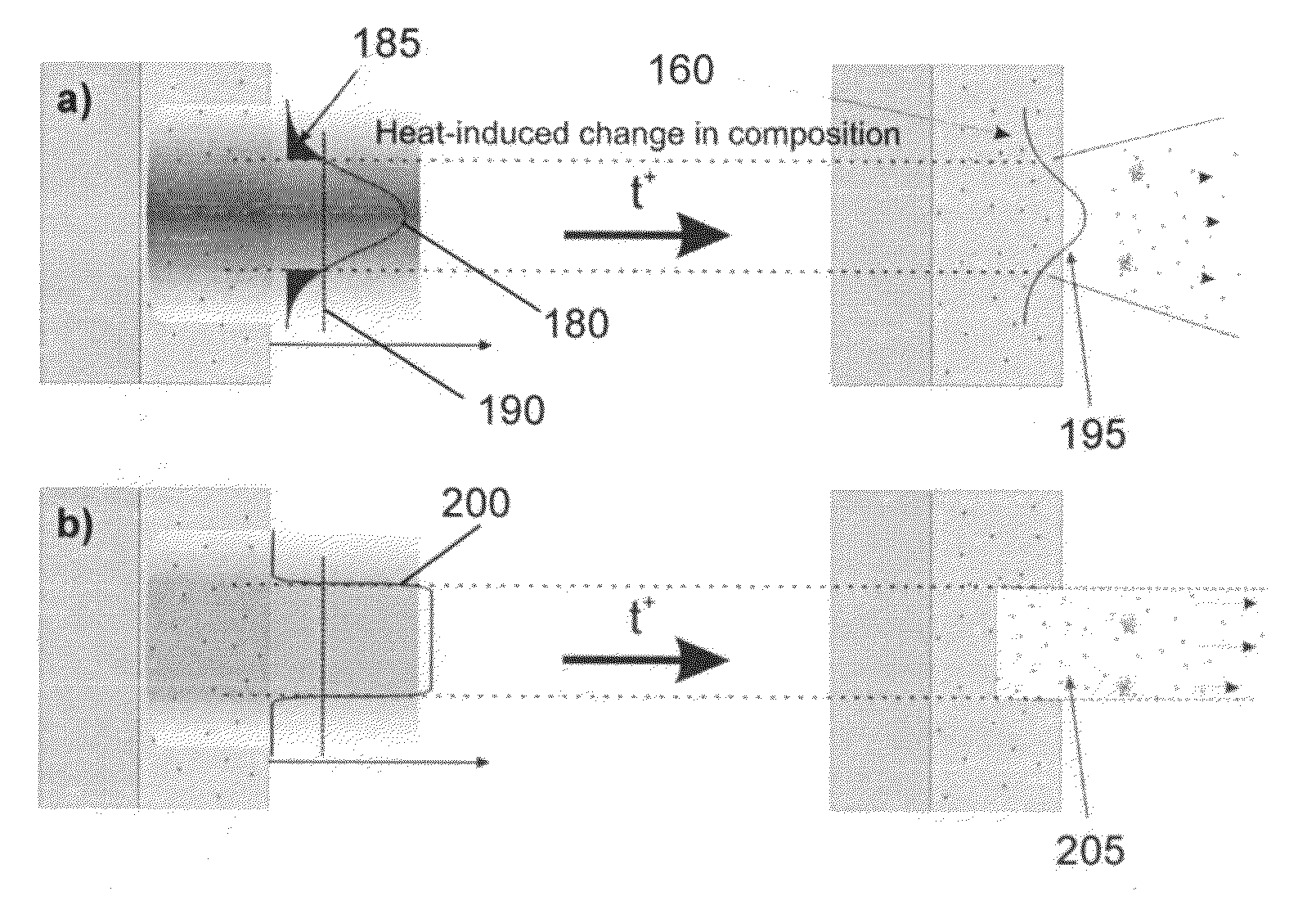
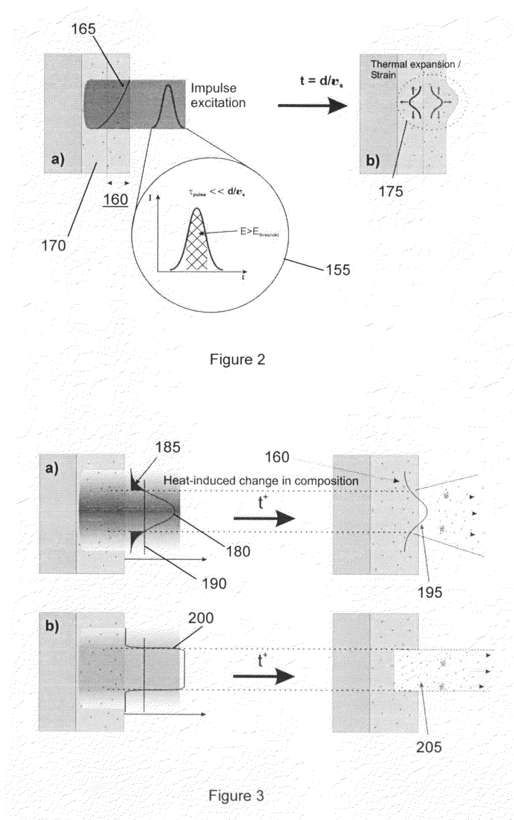
Methods and systems are provided for the soft desorption of analyte from a sample, in which an optical beam absorbed within an irradiate zone of the sample causes vibrational excitations of a component within the sample. The optical beam, providing sufficient energy to superheat the component, is provided for a time interval that is less than the time duration required for the loss of energy out of the irradiated zone due to thermal diffusion and acoustic expansion. The superheated component thus drives ablation within the irradiated zone, resulting in the soft desorption of analyte without ionization and fragmentation. The ejected ablation plume may be directed towards the inlet of a mass analysis device for detection of the desorbed analyte, which is preferably ionized by a linear resonant photo-ionization step.

Description

CROSS-REFERENCE TO RELATED APPLICATION[0001]This application claims priority to U.S. Provisional Application No. 61 / 202,161, filed on Feb. 2, 2009, and titled “Enhanced Molecular Detection Using Mass Spectroscopy with Time and Wavelength Multiplexed Laser Pulses”, the entire contents of which are incorporated herein by reference.FIELD OF THE INVENTION[0002]The present invention relates to the desorption of analyte from a sample for analytical methods. More particularly, the present invention relates to methods of sample preparation for mass spectrometry.BACKGROUND OF THE INVENTION[0003]One of the most important problems in healthcare today is the early detection of disease states, whether one is trying to detect the onset of cancer or a specific viral infection. Most current assay technologies involve microliters or milliliters of sample and have moderate detection limits that require a significant analyte concentration. On the other hand, a single drop of blood or saliva may contai...

Claims


Application Information

Patent Timeline
Patent Type & Authority Applications(United States)
IPC IPC(8): H01J49/04G01N1/28H01J49/40H01J49/42B23K26/42
CPCG01N1/405Y10T436/25Y10T436/25125H01J49/0463
Inventor MILLER, R.J. DWAYNE
Owner LIGHT MATTER INTERACTION INC
Learn More