Pitch detection method and apparatus
a pitch detection and pitch detection technology, applied in the field of speech and audio signal encoding technology, can solve the problems of low pitch detection complexity, high lossy encoding compression efficiency, and inability to guarantee the quality of reconstructed speech and audio signals, so as to reduce complexity of algorithm and ensure accuracy of pitch detection
- Summary
- Abstract
- Description
- Claims
- Application Information
AI Technical Summary
Benefits of technology
Problems solved by technology
Method used
Image
Examples
embodiment 1
[0026]This embodiment provides a pitch detection method, which is hereinafter described in detail with reference to the accompanying drawings.
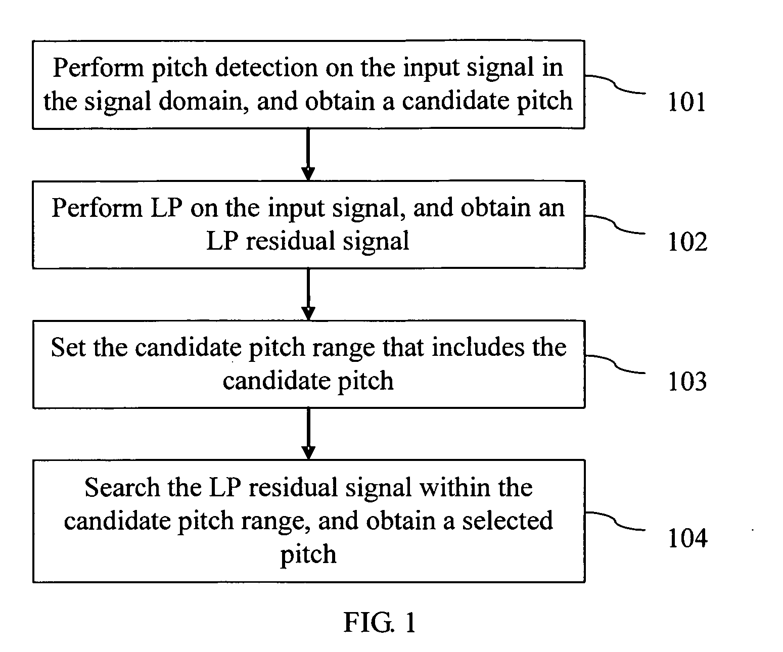
[0027]FIG. 1 is a flowchart of a method according to one embodiment of the present invention. As shown in FIG. 1, the pitch detection method includes the following steps:
[0028]Block 101: Perform pitch detection on the input signal in the signal domain, and obtain a candidate pitch.
[0029]In this embodiment, some pre-processing operations may be performed on the input signal prior to the pitch detection in the signal domain, for example, low pass filtering, median clipping and down sampling; then pitch search is performed on the pre-processed signal. Thus, before block 101, the method may further include pre-processing the input signal and obtaining a pre-processed signal. The process of pre-processing may include: performing low pass filtering and down sampling on the input signal, and obtaining a down sampled signal. In this case, the down sam...
embodiment 2
[0040]This embodiment provides another pitch detection method, which is hereinafter described in detail with reference to the accompanying drawings.
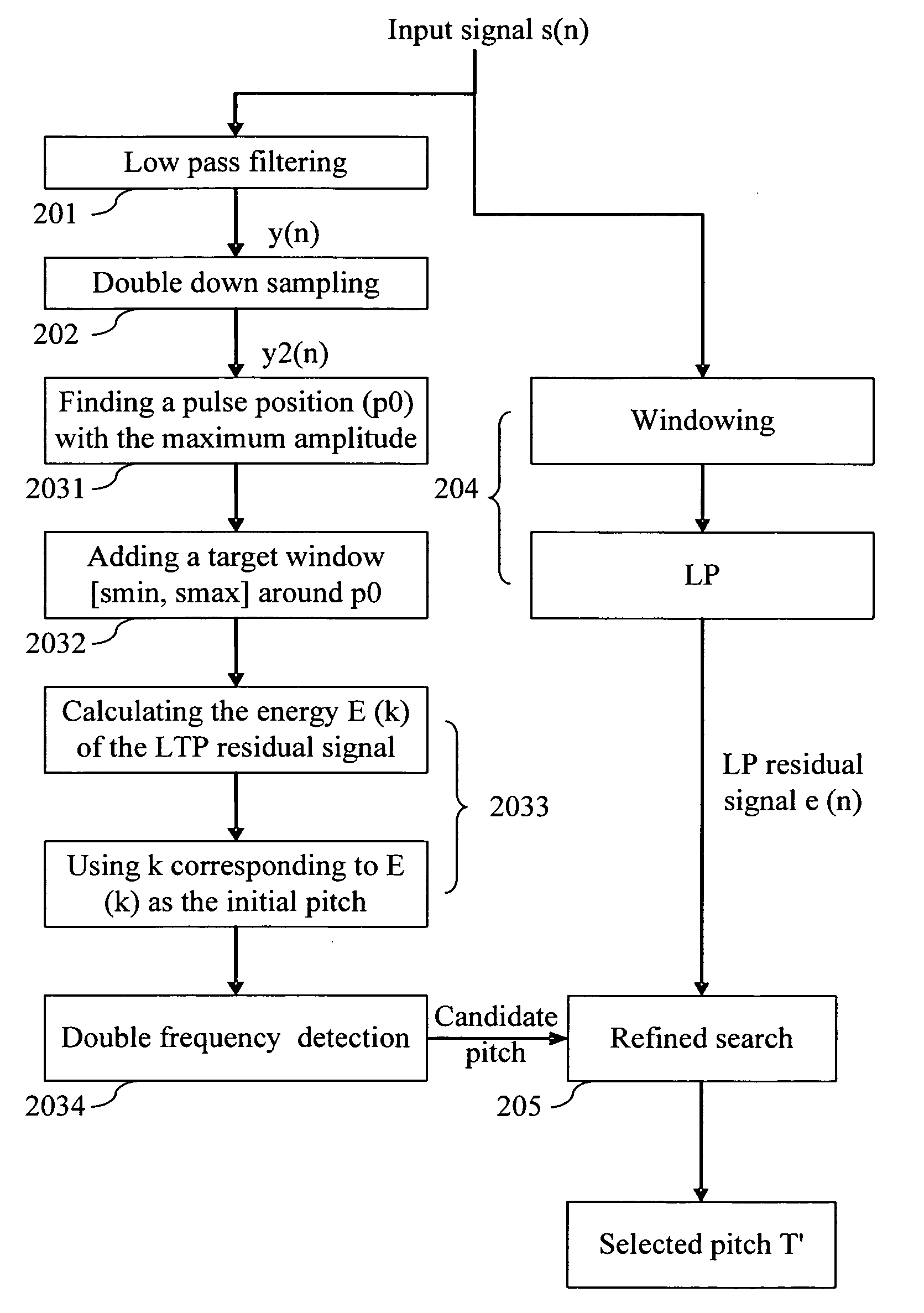
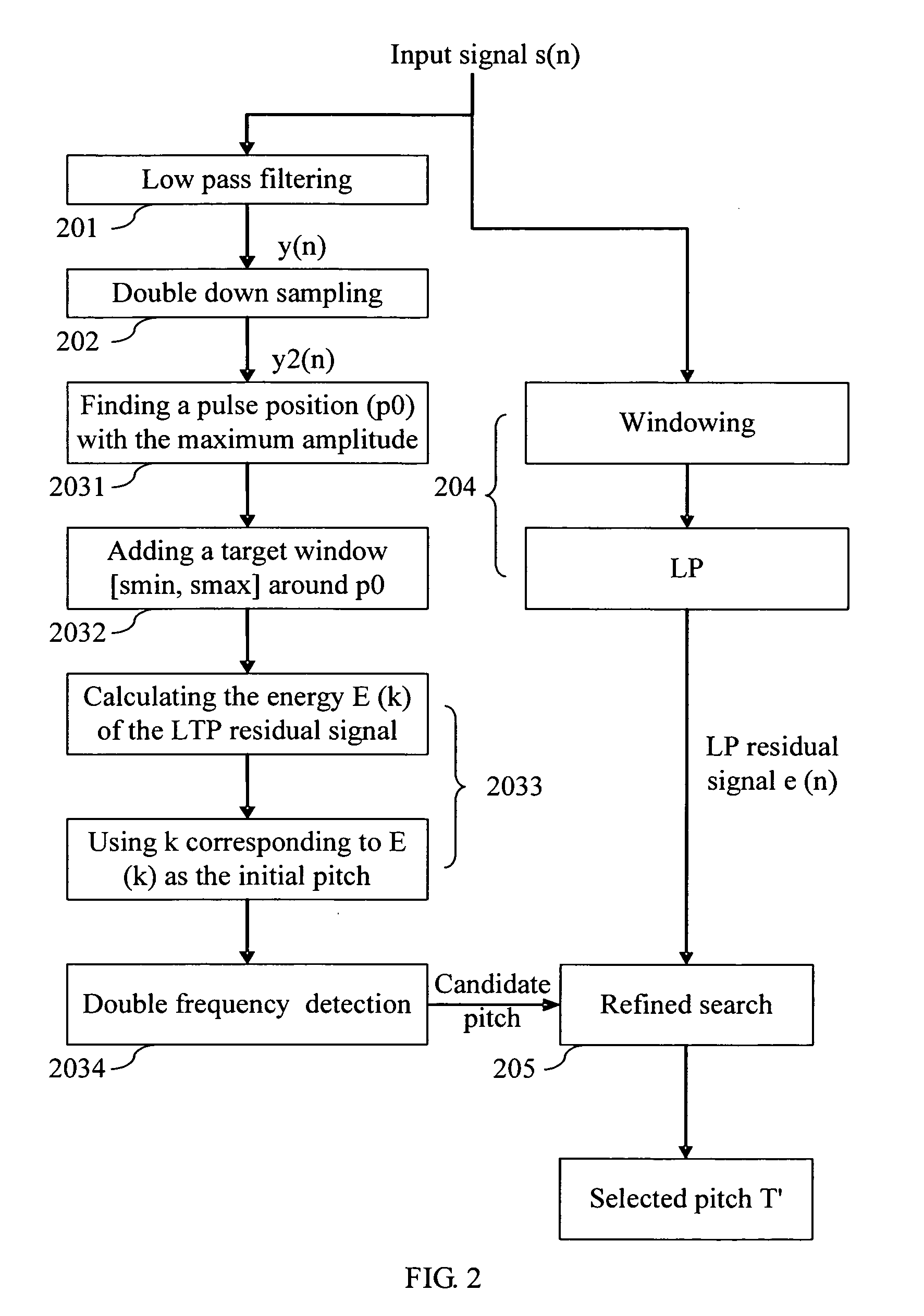
[0041]FIG. 2 is a flowchart of a method according to another embodiment of the present invention. The method takes the frame length (L) of 160 samples as an example. As shown in FIG. 2, the method includes the following steps:
[0042]Block 201: Perform low pass filtering on the input signal s(n), and obtain a low pass filtered signal y(n):
y(n)=s(n)+y(n-1)2,
where n=0, 1, . . . , L
[0043]Block 202: The low pass filtered signal y(n) is downsampled, and obtain a downsampled signal y2(n):
y2(n)=y(2n), where
n=0,1,…,(L2-1).
[0044]Block 203: Pitch search is performed for the downsampled signal y2(n).
[0045]Because the pitch generally ranges from 2 ms to 20 ms, the pitch range is limited to [20, 83] (8 kHz sampling) in this embodiment and the pitch parameter may be encoded with 6-bit in consideration of encoding efficiency and performance. In addition,...
embodiment 3
[0066]This embodiment provides a pitch detection apparatus, which is hereinafter described in detail with reference to the accompanying drawing.
[0067]FIG. 4 is a block diagram illustrating components of the apparatus according to one embodiment of the present invention. As shown in FIG. 4, the pitch detection apparatus includes:
[0068]a signal-domain pitch detecting unit 41, configured to detect the pitch of the input signal in the signal domain, and obtain a candidate pitch;
[0069]a linear predicting unit 42, configured to perform LP on the input signal, and obtain an LP residual signal;
[0070]a setting unit 43, configured to set a candidate pitch range that includes the candidate pitch; and a residual-domain refined detecting unit 44, configured to search for the LP residual signal refiinedly within the candidate pitch range, and obtain a selected pitch.
[0071]The components of the apparatus provided in this embodiment are configured to implement each step of the method in the Embodim...
PUM
 Abstract
Description
Claims
Application Information
 - R&D
- Intellectual Property
- Life Sciences
- Materials
- Tech Scout
- Unparalleled Data Quality
- Higher Quality Content
- 60% Fewer Hallucinations
Browse by: Latest US Patents, China's latest patents, Technical Efficacy Thesaurus, Application Domain, Technology Topic, Popular Technical Reports.
© 2025 PatSnap. All rights reserved.Legal|Privacy policy|Modern Slavery Act Transparency Statement|Sitemap|About US| Contact US: help@patsnap.com


