
Device and method for fine or finest processing of a rotationally symmetric work piece surface

Inactive Publication Date: 2010-08-19
SUPFINA GRIESHABER
View PDF2 Cites 2 Cited by
  • Summary
  • Abstract
  • Description
  • Claims
  • Application Information

AI Technical Summary

Benefits of technology

[0007]The pressing plane is therefore positioned eccentrically relative to the axis of rotation and thus offset toward the two guidance mechanisms. Surprisingly, this offset of the pressing plane is sufficient to exert a lateral force that presses the work piece toward the guidance mechanisms. This makes it possible to dispense with a third guidance mechanism. At the same time, it is not necessary to coordinate different distances between the first two guidance mechanisms from the axis of rotation of the work piece and a direction of rotation of the work piece.
[0019]It is further preferred if the holder is supported on a linear drive that can be moved toward and away from the drive mechanism in a direction parallel to the axis of rotation. This makes it possible to produce pressing forces to be exerted on the drive mechanism using the linear drive.

Problems solved by technology

In the fine and finest processing of a rotationally symmetric work piece surface of a work piece, radial clamping poses the problem that rotationally symmetric work piece surfaces can be damaged by contact with the clamping tool.
However, it is disadvantageous that, due to the offset between the axis of rotation of the drive mechanism and the real axis of rotation of the work piece, the latter moves in the radial direction relative to the drive mechanism and / or the pressing mechanism so that the end surfaces of the work piece rub against the corresponding facing surfaces of the drive mechanism and / or the pressing mechanism.
This can damage the face-end surfaces of the work piece and / or the facing surfaces of the drive mechanism and / or the pressing mechanism.
At the same time, stick-slip effects can occur with the consequence that the work piece cannot be processed with the necessary precision and, in particular, circular runout tolerances can no longer be complied with.

Method used


Image

  • Device and method for fine or finest processing of a rotationally symmetric work piece surface
  • Device and method for fine or finest processing of a rotationally symmetric work piece surface
  • Device and method for fine or finest processing of a rotationally symmetric work piece surface

Examples


first embodiment

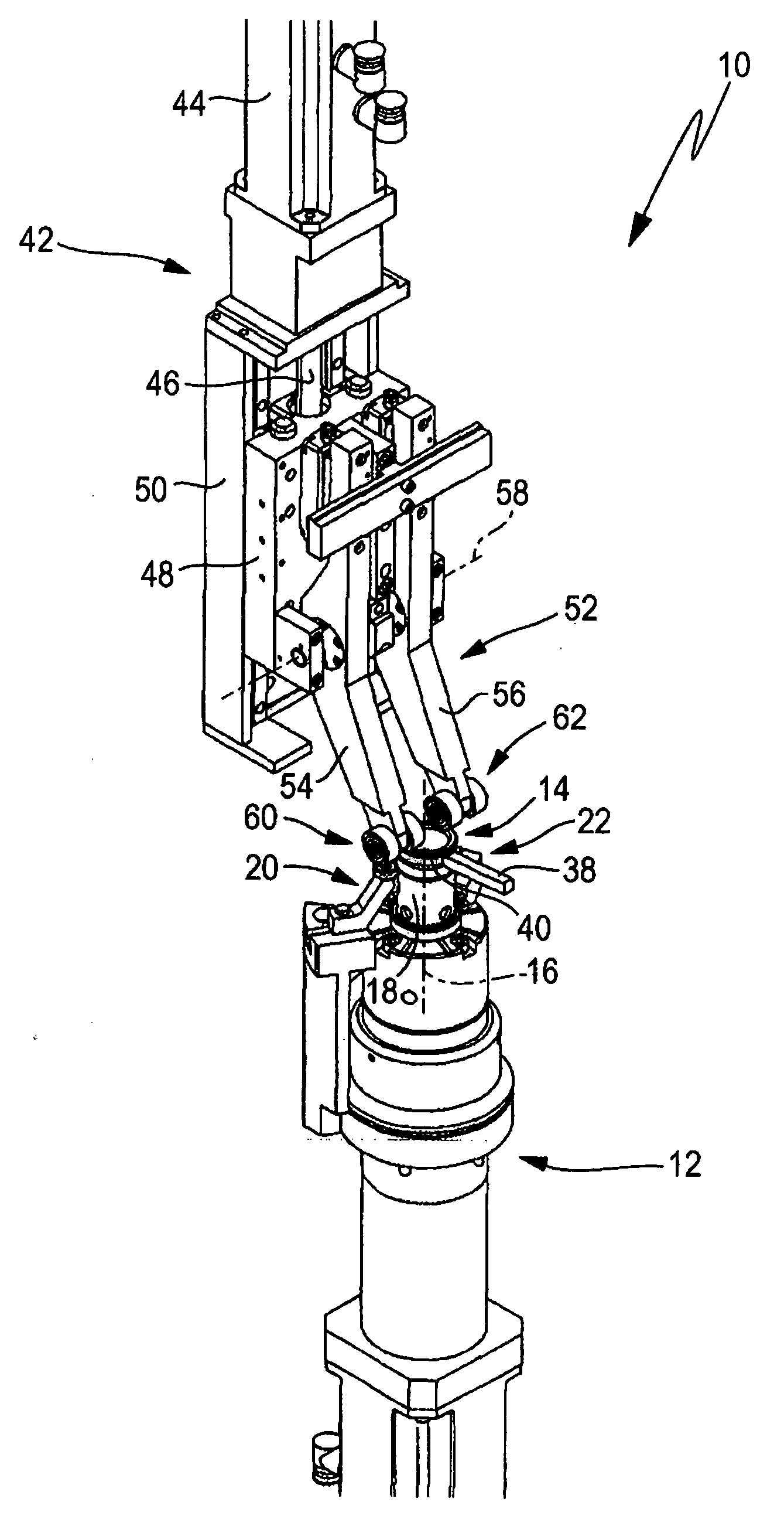
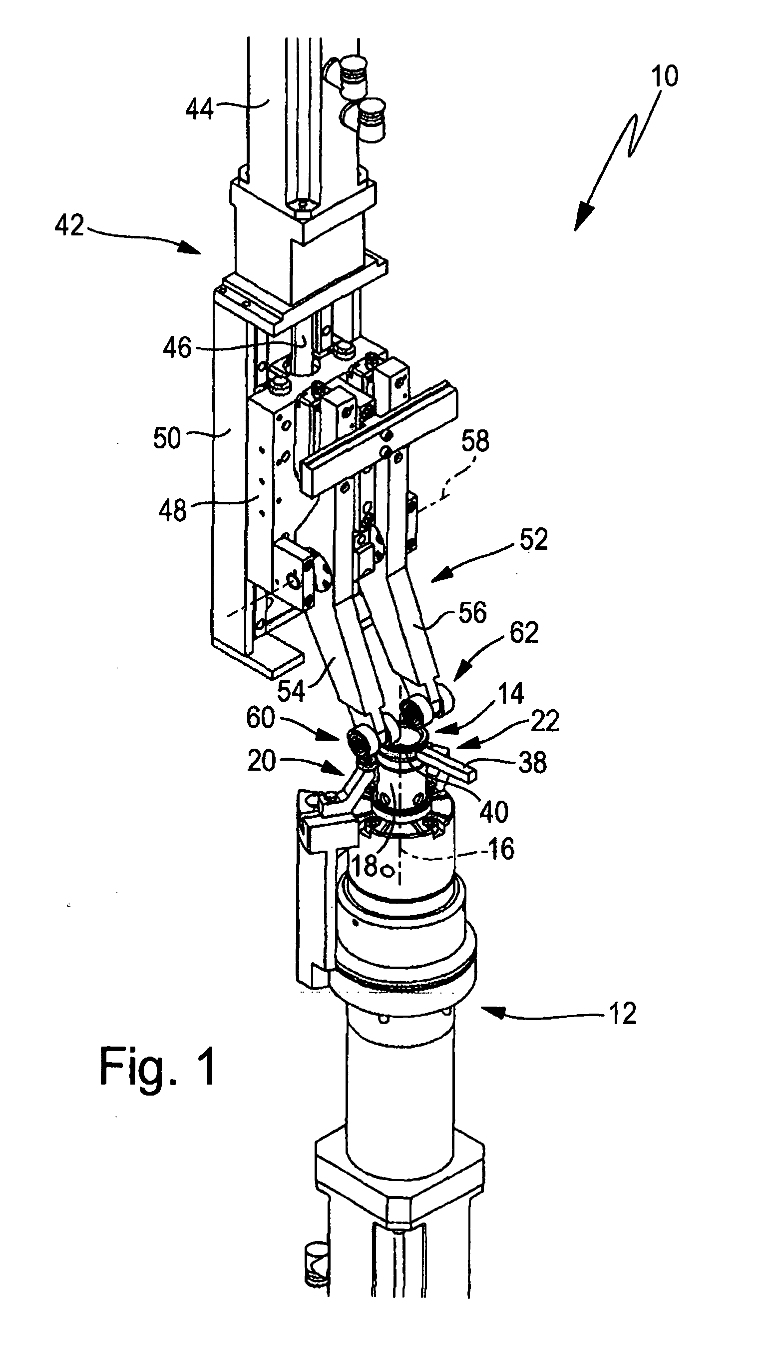
[0032]a device for fine or finest processing is shown in FIG. 1 and designated in its totality with reference sign 10. The device 10 is, in particular, a device for finish-machining a work piece.

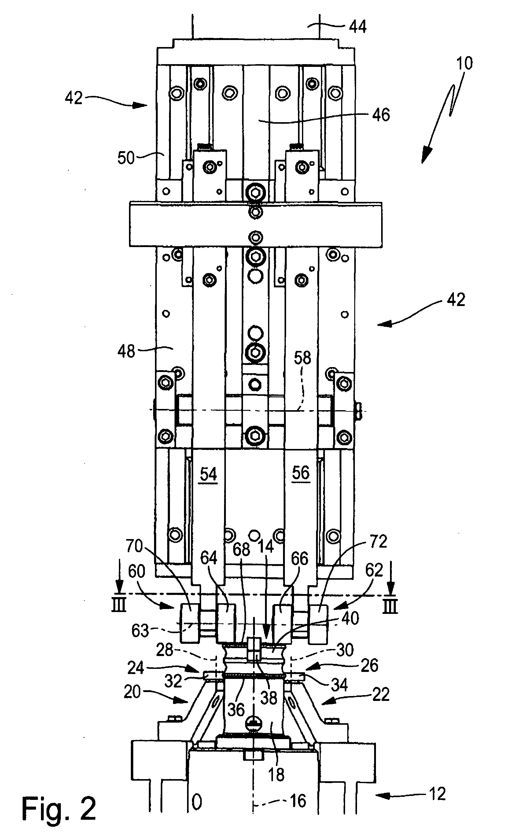
[0033]The device 10 comprises a drive mechanism 12 that is disposed at the lower end and is used to drive a work piece 14 around an axis of rotation 16. The drive mechanism 12 comprises a work piece holder 18 onto which the work piece 14 can be placed upon the latter's lower end face.

[0034]The work piece 14 can be driven by frictional connection with a contact surface of the work piece holder 18 around the axis of rotation 16. To prevent radial outward displacement of the work piece 14, the device 10 comprises a first guidance mechanism 20 and a second guidance mechanism22.

[0035]The guidance mechanisms 20 and 22 each have a guidance roller 24 and 26 that can be rotated around stationary guidance roller axles 28 and 30. The guidance roller axles 28 and 30 extend, in particular, parallel to th...

second embodiment

[0056]the device 10 has a tool 38 that is positioned within the ring-shaped work piece 14 so that a work piece surface 40 of the work piece 14 facing radially inward can be processed. For example, work piece 14 is an outer shell of a roller bearing and the work piece surface 40 is a contact surface for a rolling element.

[0057]For all other aspects, please refer to the description of the first embodiment of the device 10 for the structure and method of functioning of the second embodiment.


PUM

PropertyMeasurementUnit
Angleaaaaaaaaaa
Distanceaaaaaaaaaa
Symmetryaaaaaaaaaa

Abstract

A device for fine or finest processing of a rotationally symmetric work piece surface of a work piece (14), with a drive mechanism (12) for driving the work piece (14) around an axis of rotation (16), two guidance mechanisms (20, 22) acting in radial directions with respect to the axis of rotation (16) and at least one tool (38) acting in a radial direction, and a pressing mechanism (42) for pressing the work piece (14) against the drive mechanism (12), wherein the work piece (14) can be disposed between the drive mechanism (12) and the pressing mechanism (42). The pressing mechanism (42) acts in a pressing plane (74) that is offset from the axis of rotation (16) towards a space (78) in which the guidance mechanisms (20, 22) are disposed.

Description

[0001]This application claims benefit of provisional application No. 61 / 152,269 filed on Feb. 13, 2009 the entire disclosure of which is hereby incorporated by reference.BACKGROUND OF THE INVENTION[0002]The invention relates to a device for fine or finest processing of a rotationally symmetric work piece surface of a work piece, with a drive mechanism for driving the work piece around an axis of rotation, with two guidance mechanisms acting in radial directions with respect to the axis of rotation, and at least one tool acting in a radial direction, with a pressing mechanism for pressing the work piece against the drive mechanism, wherein the work piece can be disposed between the drive mechanism and the pressing mechanism as seen in the direction of the axis of rotation.[0003]In the fine and finest processing of a rotationally symmetric work piece surface of a work piece, radial clamping poses the problem that rotationally symmetric work piece surfaces can be damaged by contact wit...

Claims


Application Information

Patent Timeline
IPC IPC(8): B24B5/04B24B19/00
CPCB24B5/02B24B41/06B24B19/06
Inventor ROSER, JUERGENWELLE, DANIEL
Owner SUPFINA GRIESHABER
Learn More