
Stator for an electric motor and electric motor

Pending Publication Date: 2022-03-31
BROSE FAHRZEUGTEILE SE & CO KGAA WUERZBURG
View PDF0 Cites 0 Cited by
  • Summary
  • Abstract
  • Description
  • Claims
  • Application Information

AI Technical Summary

Benefits of technology

The invention is a joining element that is used to connect two parts together. The joining element has a flat base and a raised part that sticks out from the base. It forms a connection with a motor housing where the stator is inserted. This connection has certain functions such as protecting, damping, and positioning. The technical effect of this invention is to improve the connection between two parts and make it more reliable.

Problems solved by technology

In particular in an electric steering motor of a motor vehicle, the stator can deform as a result of electromagnetic forces caused by operation, wherein such deformations can become very large, for example in the case of a 10-pole electric motor, so that a high level of structure-borne noise is transmitted to the motor housing accommodating the stator.

Method used


Image

  • Stator for an electric motor and electric motor
  • Stator for an electric motor and electric motor
  • Stator for an electric motor and electric motor

Examples


Embodiment Construction

[0032]Corresponding parts are marked with the same reference signs in all figures.

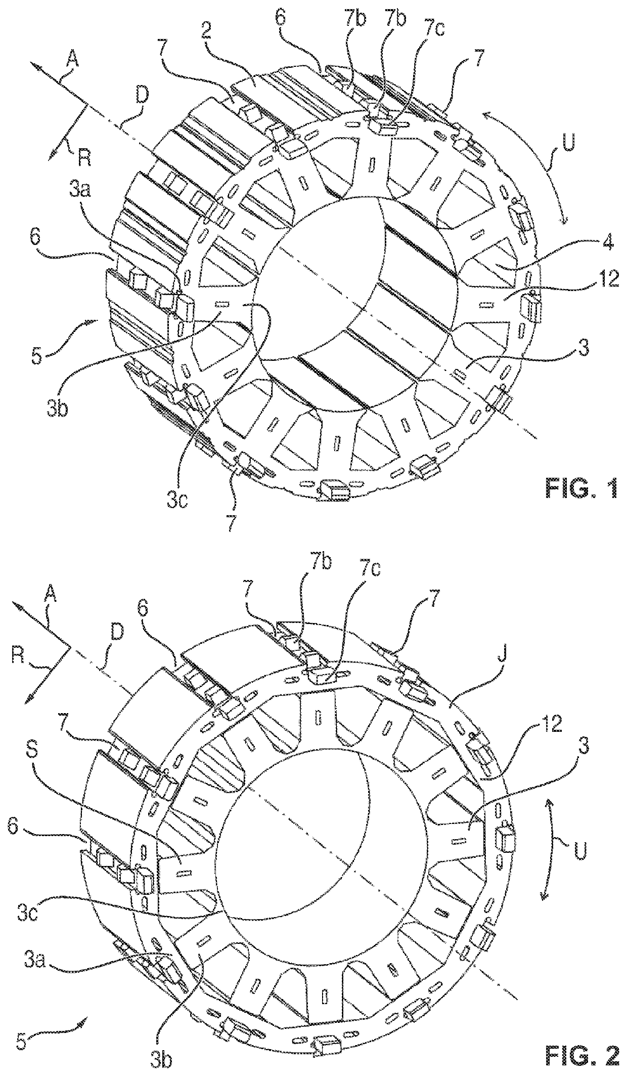
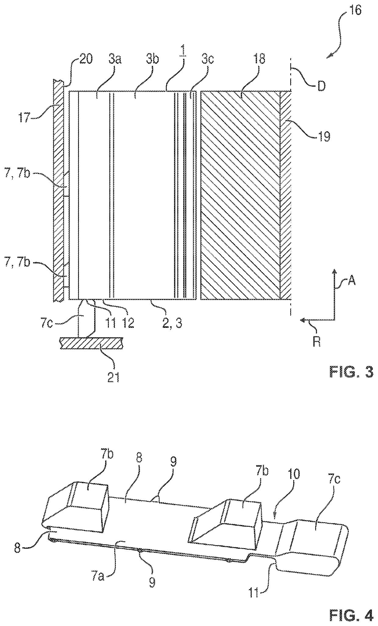
[0033]Referring now to the figures of the drawings in detail and first, particularly to FIGS. 1 and 2 thereof, there is shown a stator 1, the stator base body 2 of which has a number of stator teeth 3, twelve in the embodiment example, which extend inwardly in the radial direction R (radially) towards a central axis of rotation D shown in the drawing. Free spaces 4 are formed between the stator teeth 3, in which the windings of coils are accommodated in a manner not shown in more detail, which are connected to each another in a star or delta connection to form the stator or rotating field winding.

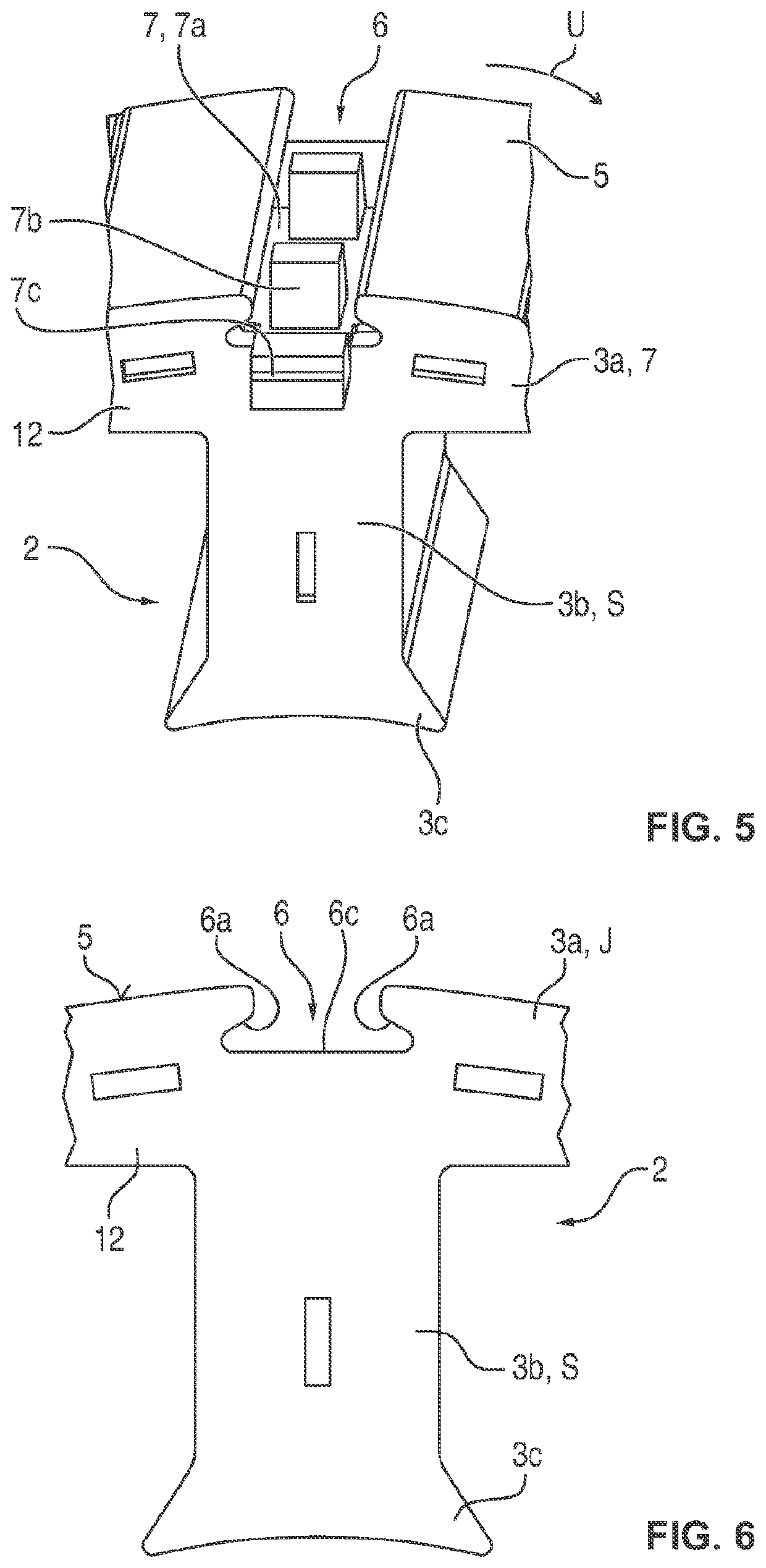
[0034]With reference also to FIGS. 5 and 6, the stator base body 2 has, in the region of each stator tooth 3, an azimuthal yoke or return section 3a extending in the circumferential direction U (FIG. 1) and a radial leg 3b, and an azimuthal pole piece section 3c again extending in the circumferential direction...


PUM


Abstract

A stator for an electric motor has a stator base body, which has stator teeth arranged in a star shape and a stator yoke, and on whose outer circumference a number of axial slots are provided, into which joining elements projecting radially from the circumference of the stator base body are radially inserted in a form-fitting manner.

Description

CROSS-REFERENCE TO RELATED APPLICATION[0001]This application is a continuation, under 35 U.S.C. § 120, of copending International Patent Application PCT / EP2020 / 065953, filed Jun. 9, 2020, which designated the United States; this application also claims the priority, under 35 U.S.C. § 119, of German Patent Application DE 10 2019 208 426.5, filed Jun. 11, 2019; the prior applications are herewith incorporated by reference in their entirety.FIELD AND BACKGROUND OF THE INVENTION[0002]The invention relates to a stator for an electric motor, in particular for an electric steering motor of a motor vehicle, with a stator base body having stator teeth arranged in a star shape and a stator yoke. It further relates to an electric motor with such a stator, which is arranged in a motor housing.[0003]An electric motor as an energy converter of electrical energy into mechanical energy has a stator, which forms the stationary motor part, and a rotor, which forms the moving motor part. In the case o...

Claims


Application Information

Patent Timeline
IPC IPC(8): H02K1/18H02K1/14H02K5/24
CPCH02K1/185H02K5/15H02K5/24H02K1/148H02K1/146
Inventor KOCH, KEVINDUENCHER, MICHAELDEHN, JOCHEN
Owner BROSE FAHRZEUGTEILE SE & CO KGAA WUERZBURG
Learn More