
Apparatus for supplying liquid nitrogen

a technology for liquid nitrogen and apparatus, applied in the direction of insulated conductors, containers, cables, etc., can solve the problems of high installation cost, high maintenance cost, and high cost of gas-liquid separators b>3/b>,

Inactive Publication Date: 2010-08-12
LG CABLE LTD (KR)
View PDF3 Cites 0 Cited by
  • Summary
  • Abstract
  • Description
  • Claims
  • Application Information

AI Technical Summary

Benefits of technology

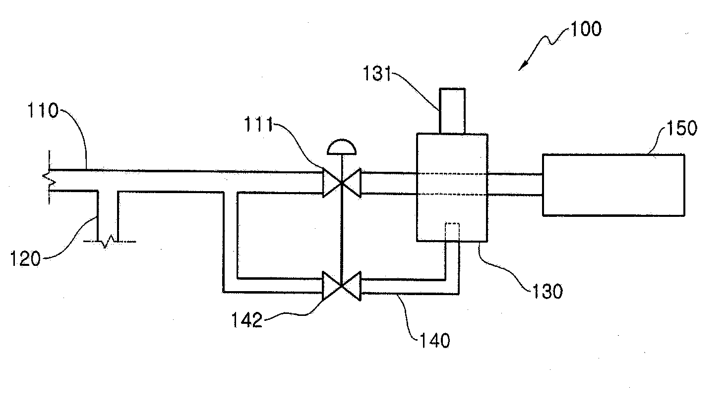
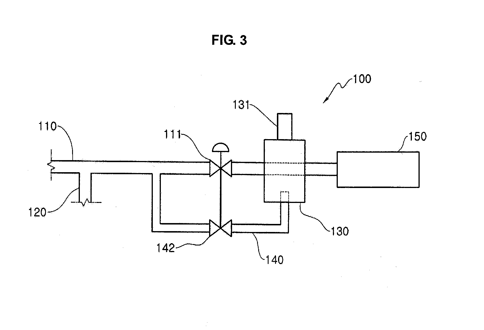
The patent describes an apparatus for supplying liquid nitrogen for a decompression device of a superconducting cable. The apparatus includes a liquid nitrogen supply line, a bypass pipe, and an expansion unit. The expansion unit absorbs heat from the liquid nitrogen before it is introduced to the decompression device. The apparatus does not require a vacuum-insulated gas-liquid separator, reducing manufacture costs and preventing waste of nitrogen gas. The apparatus is designed to be directly connected to the high-temperature, high-pressure liquid nitrogen supply line, eliminating the need for a separate gas-liquid separator. The apparatus is kept at a high temperature even at the front end of the valve, allowing for its installation regardless of pressure difference. The apparatus also allows for rapid operation of the decompression device by cooling the expansion unit in advance.

Problems solved by technology

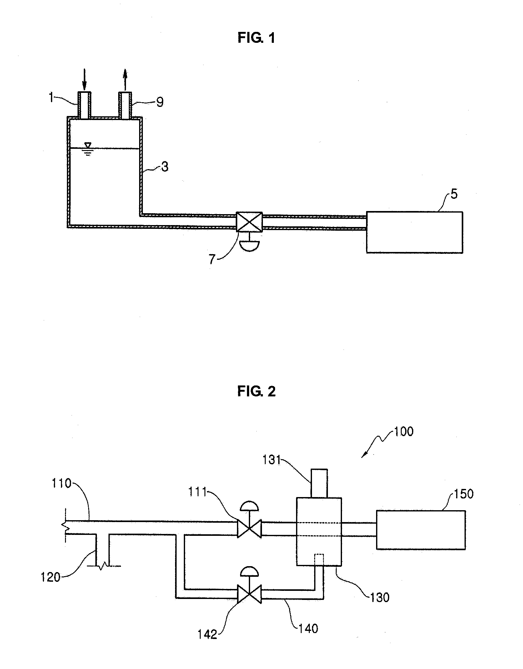
Such an apparatus for supplying liquid nitrogen used for a decompression device of a superconducting cable, configured as above, has a complicated structure since the gas-liquid separator 3 should be separately installed to supply liquid nitrogen at an atmospheric pressure, and the installation cost is high.
The gas-liquid separator 3 is a vacuum insulating tank, which is expensive.
Also, while liquid nitrogen is filled in the gas-liquid separator 3, a large amount of nitrogen gas is generated and discharged to the air, which increases a maintenance cost.
In case of the gas-liquid separator, a certain amount of liquid nitrogen should be filled at ordinary times, but the liquid nitrogen filled in the gas-liquid separator is evaporated due to the external heat, which increases the consumption of liquid nitrogen.

Method used


Image

  • Apparatus for supplying liquid nitrogen
  • Apparatus for supplying liquid nitrogen
  • Apparatus for supplying liquid nitrogen

Examples


Embodiment Construction

[0028]Exemplary embodiments now will be described more fully hereinafter with reference to the accompanying drawings, in which exemplary embodiments are shown. This disclosure may, however, be embodied in many different forms and should not be construed as limited to the exemplary embodiments set forth therein. Rather, these exemplary embodiments are provided so that this disclosure will be thorough and complete, and will fully convey the scope of this disclosure to those skilled in the art. In the description, details of well-known features and techniques may be omitted to avoid unnecessarily obscuring the presented embodiments.

[0029]The terminology used herein is for the purpose of describing particular embodiments only and is not intended to be limiting of this disclosure. As used herein, the singular forms “a”, “an” and “the” are intended to include the plural forms as well, unless the context clearly indicates otherwise. Furthermore, the use of the terms a, an, etc. does not de...


PUM


Abstract

An apparatus for supplying liquid nitrogen for a decompression device: includes a liquid nitrogen supply line extending such that high-temperature, high-pressure liquid nitrogen is introduced to a decompression device; a bypass pipe diverging from the liquid nitrogen supply line; and an expansion unit installed at the bypass pipe to evaporate the liquid nitrogen into nitrogen gas. The expansion unit is disposed to absorb heat from the liquid nitrogen in the liquid nitrogen supply line before being introduced to the decompression device.

Description

CROSS-REFERENCE TO RELATED APPLICATION[0001]This application claims priority to Korean Patent Application No. 10-2009-0011001, filed on Feb. 11, 2009, and all the benefits accruing therefrom under 35 U.S.C. §119, the contents of which in its entirety are herein incorporated by reference.BACKGROUND[0002]1. Field[0003]This disclosure relates to an apparatus for supplying liquid nitrogen, and more particularly to an apparatus for supplying liquid nitrogen used for a decompression device of a superconducting cable.[0004]2. Description of the Related Art[0005]Superconductivity is a phenomenon that an electric resistance of a conductor becomes zero at ultra-low temperatures, and a superconducting cable is a power cable for realizing such a phenomenon. Liquid nitrogen is used to realize the superconductivity, and a conductor may have superconducting characteristics thanks to an ultra-low temperature of the liquid nitrogen.[0006]Liquid nitrogen is filled while being in contact with a superc...

Claims


Application Information

Patent Timeline
Patent Type & Authority Applications(United States)
IPC IPC(8): F17C7/02F17C13/00
CPCF17C7/02F17C13/00F17C2205/0323F17C2221/014F17C2223/0161F17C2270/0527F17C2225/0161F17C2225/033F17C2227/0339F17C2227/0358F17C2223/033H01B7/423H01B12/00H01B13/00
Inventor KIM, CHOON DONGLEE, SU KILJANG, HYUN MANCHOI, CHANG YOUL
Owner LG CABLE LTD (KR)
Learn More