Ballast retaining structure, bedded track

a technology of ballast retaining structure and bedded track, which is applied in the direction of track superstructure, roads, constructions, etc., can solve the problems of easy difficulty in adjusting the height deviation of the track, so as to suppress the deformation reduce the displacement of the track bed, and reduce the effect of labor and tim

Inactive Publication Date: 2010-08-05
CENTRAL JAPAN RAILWAY COMPANY
View PDF5 Cites 3 Cited by
  • Summary
  • Abstract
  • Description
  • Claims
  • Application Information

AI Technical Summary

Benefits of technology

[0012]The present invention, which has been made in view of these problems, has an object to provide a technique which does not require heavy equipment and can suppress deformation of a track bed of a bedded track while achieving a good constructability and lower costs.Means for Solving the Problems
[0043]According to this configuration, the second connection member inserted through mutually opposing communication holes formed in the bag-like objects constituting the second layered body is located inside the second layered body, the second connection member connects adjacent bag-like objects with each other, and a leading end of the second connection member is buried into the roadbed. As a result, the bag-like objects mutually connected by the second connection member are less likely to be displaced in the transverse direction of the track bed, and thereby the ballast retaining structure is less likely to be displaced. That is, by applying a prestress (a binding force) to the second layered body by the second connection member, an improved shear stress of the second layered body can be obtained, and thereby deformation of the track bed can be suppressed even when an impulsive stress is applied to the track bed, for example, at a high temperature or during an earthquake. Thus, safe running of trains can be secured.

Problems solved by technology

However, in the track bed using the ballast as described above, individual gravel particles or crushed stones tend to move in a vicinity of a surface of the track bed.
Such an operation to correct the height deviation of the track requires considerable work and cost.
However, in an area from a toe of slope to a top of slope of the track bed, individual gravel particles or crushed stones tend to move in a vicinity of a surface of the track bed as described above, and the track bed is easily deformed due to passing train loads, a bulging force resulting from a rail axial force at a high temperature, stress by an earthquake or the like, or subsidence of an embankment structure, and a height deviation of the track is sometimes caused.
This leads to problems in construction work as follows: (1) It is required to transport the ballast retaining structures by a maintenance car or the like from a storage area to a construction cite at the time of construction.
Also, it is known that a construction method using the ballast retaining structure 1010 generally results in higher costs.

Method used


Image

  • Ballast retaining structure, bedded track
  • Ballast retaining structure, bedded track
  • Ballast retaining structure, bedded track

Examples


first embodiment

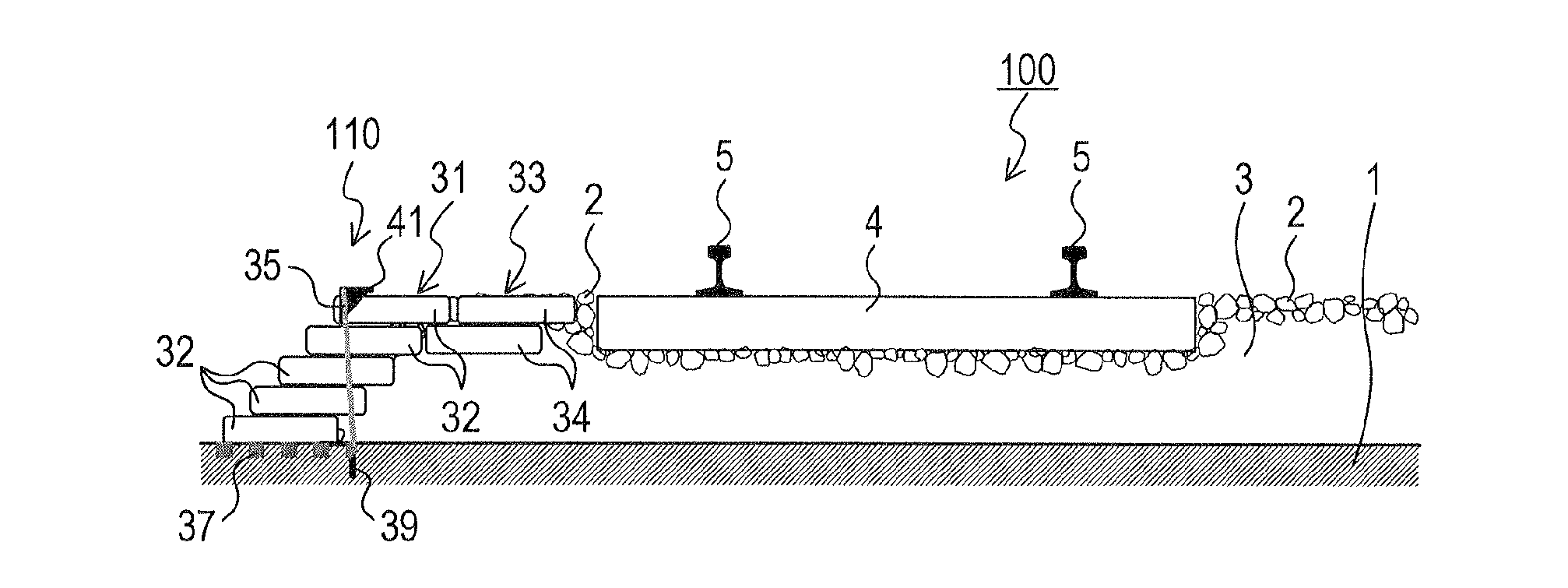
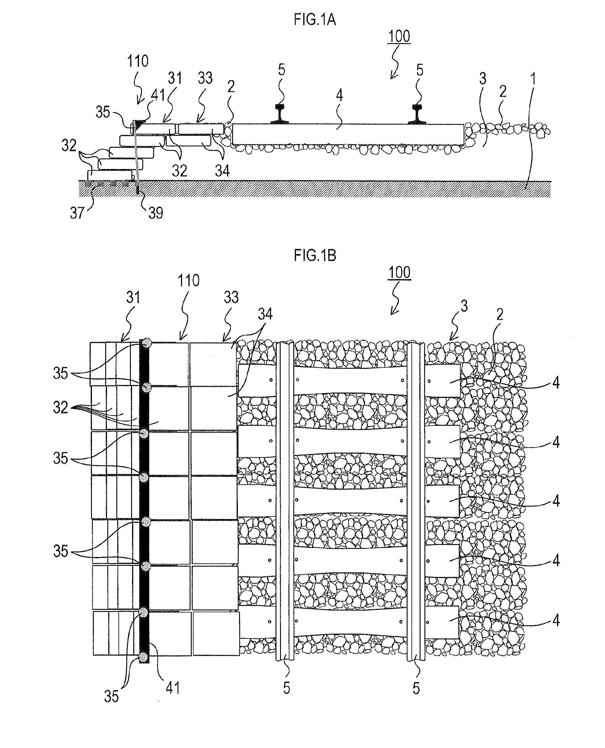
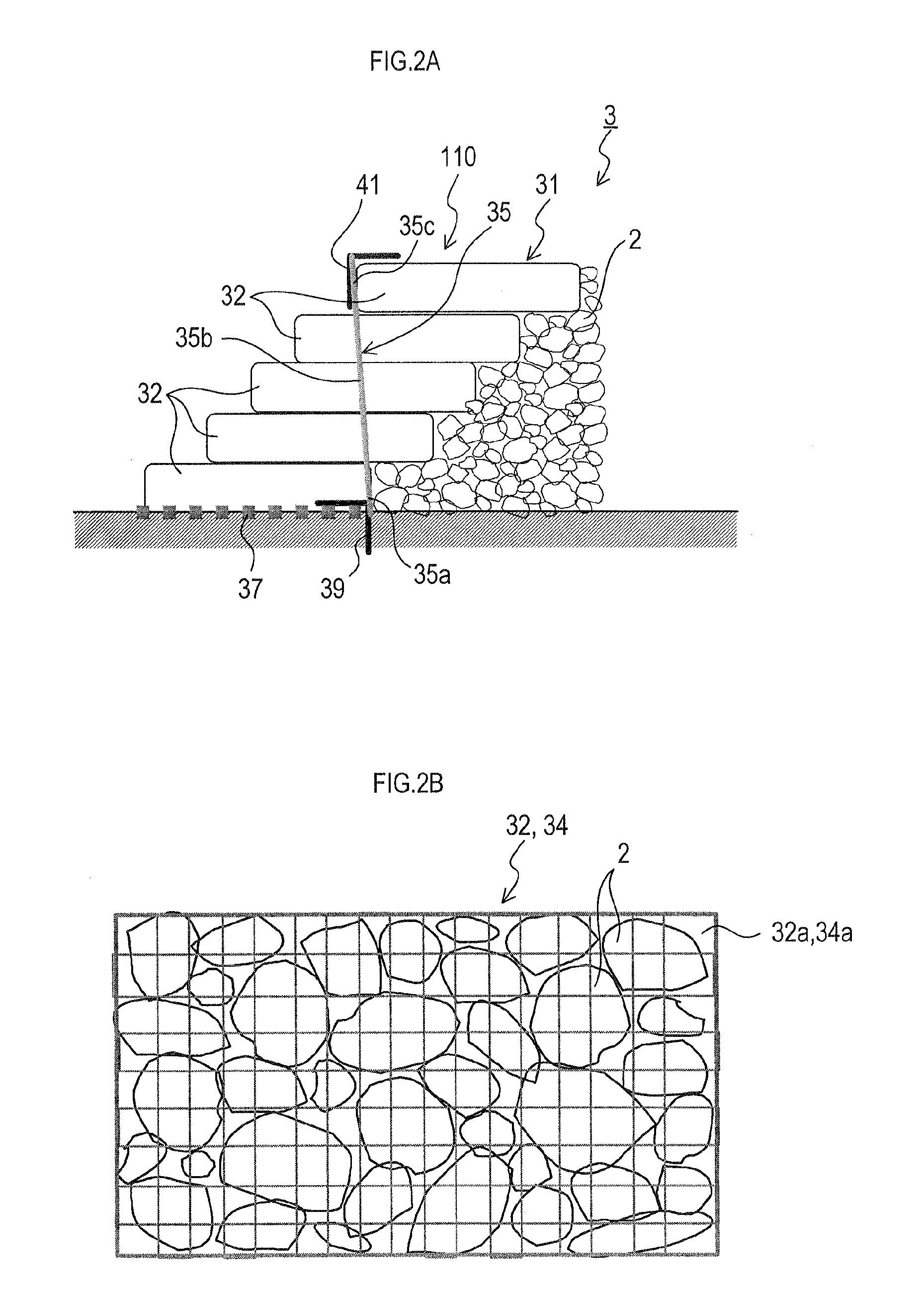
[0052]FIG. 1A is a front cross-sectional view showing a configuration of a bedded track 100 in the present embodiment. FIG. 1B is a plan view of the bedded track 100 in the present embodiment, FIG. 2A is a cross-sectional view showing a configuration of a ballast retaining structure 110 in the present invention, and FIG. 2B is an explanatory view showing a configuration of a bag-like object 32 made of net formed in a bag shape.

[0053][Explanation of Configuration of Bedded Track 100]

[0054]As shown in FIG. 1A, FIG. 1B and FIG. 2A, the bedded track 10 includes a track bed 3, formed by laying ballast 2, such as crushed stones, on a roadbed 1, tamping the ballast 2 so as to form a bed-like structure having a predetermined cross-sectional shape, such as a trapezoid, and extending the bed-like structure in an extending direction of the bedded track 100; a plurality of sleepers 4 (only one sleeper 4 is shown in FIG. 1A) disposed on the track bed 3 such that a longitudinal direction of each ...

second embodiment

[0082]In the first embodiment described above, the layered body 33 to be provided between the layered body 31 and the sleepers 4 is disposed so as to contact the layered body 31, and the ballast 2 is laid between the layered body 33 and the sleepers 4. In contrast, a second embodiment shown in FIG. 3A has a feature that the layered body 33 to be provided between the layered body 31 and the sleepers 4 is disposed so as to contact both of the layered body 31 and the sleepers 4, in order to reduce, in a track bed 203, a width of the ballast 2 laid between the layered body 31 and the sleepers 4.

[0083]A configuration of a bedded track 200 in the second embodiment will be described hereinafter. Note that FIG. 3A is a cross-sectional view showing the configuration of the bedded track 200 in the second embodiment.

[0084]Since the second embodiment has a lot of components in common with the first embodiment, the same reference numerals as in the first embodiment are used and detailed descript...

third embodiment

[0089]In the first embodiment described above, the plurality of sleepers 4 are disposed on the track bed 3 such that the longitudinal direction of each sleeper is perpendicular to the extending direction of the track bed 3; and a pair of rails 5 fastened to upper surfaces of the plurality of sleepers 4 along the extending direction of the track bed 3. In contrast, a third embodiment shown in FIG. 3B has a feature that a bag-like object 43 is provided between mutually adjacent sleepers 4.

[0090]A configuration of a bedded track 300 in the third embodiment will be described hereinafter. Note that FIG. 3B is a cross-sectional view showing the configuration of the bedded track 300 in the third embodiment.

[0091]Since the third embodiment has a lot of components in common with the first embodiment, the same reference numerals as in the first embodiment are used and detailed descriptions thereof are omitted herein.

[0092][Explanation of Configuration of Track Bed 303]

[0093]As shown in FIG. 3...


PUM


Abstract

A ballast retaining structure includes a first layered body constituted by a plurality of bag-like objects, each being formed in a bag shape and containing the ballast, stacked from a toe of slope to a top of slope of the track bed and disposed in the extending direction of the roadbed. The bag-like object has communication holes for communicating an inside and an outside of the bag-like object formed in at least upper and lower surfaces of the bag-like object.

Description

TECHNICAL FIELD[0001]The present invention relates to a bedded track in which a track bed is provided on a roadbed, and sleepers and rails are disposed on the track bed, and to a ballast retaining structure provided on both sides of the track bed of the bedded track.BACKGROUND ART[0002]There is a known bedded track in which a track bed is provided on a roadbed, and sleepers and rails are disposed on the track bed. Such a bedded track typically has a structure such that sleepers are disposed on the track bed formed on the roadbed, and a pair of rails are fastened to the sleepers so as to be spaced at a certain distance and parallel to each other. The track bed constituting the bedded track are made of ballast, slab, and the like, which is selected considering various conditions of each railway. A ballast bed track 1000 using ballast 2, such as gravel, crushed stones, or the like, as exemplarily shown in FIG. 5A and FIG. 5B, has been most known among them. A track bed 1003 using the b...

Claims


Application Information

Patent Timeline
Patent Type & Authority Applications(United States)
IPC IPC(8): E01B1/00
CPCE01B2/00E01B1/001E02D29/0208E01B1/00E01B37/00
Inventor SEKI, MASAKIKACHI, TAKASHIKOBAYASHI, MIKIHITOKOSEKI, JUNICHI
Owner CENTRAL JAPAN RAILWAY COMPANY
Why Eureka
Try Eureka